The following post explains the main features of mosfet IRF3205 which is fundamentally rated with drain current at a massive 110 Amps, and voltage ranging up to 55V, ideally suitable for inverter, motor control, choppers, and converter applications.
Main Features
The IRF3205 leading-edge N-Channel HEXFET® Power MOSFETs from International Rectifier implements hi-tech processing solutions to attain incredibly minimal on-resistance per silicon space.
This advantage, along with the rapid converting rate and ruggedized system layout that HEXFET power MOSFETs are popular for, offers the developer with an exceptionally cost-efficient and dependable product to be used in an array of programs.
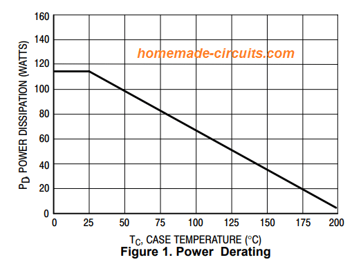
The TO-220 bundle is globally favored for most of commercial-industrial purposes at power dissipation stages to around 50 watts. The minimal thermal resistance and reduced packet price of the TO-220 play a role to its extensive recognition all through the market.
Technical Specifications
It's technical specifications may be understood with the following data:
- Continuous Drain Current, VGS @ 10V = 110 A
- Pulsed Drain Current = 390 A
- At 25°C Power Dissipation = 200 W
- Linear Derating Factor = 1.3 W/°C
- Gate-to-Source Voltage = ± 20 V
- Avalanche Current = 62 A
- Repetitive Avalanche Energy = 20 mJdv/dt
- Peak Diode Recovery dv/dt = 5.0 V/ns
- Operating Junction and Soldering Temperature, for 10 seconds = 300 (1.6mm from case )°CYou may refer to the original datasheet for more info
Pinout Details
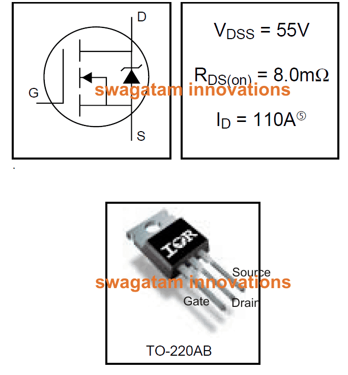
The pinout details of the mosfet IRF3205 can be witnessed in the below shown image:
Holding the device straight with its printed side towards you, the left side pin will be the gate, the center will be the drain, while the right side pinout will be the source of the mosfet
A Typical Application
Making a simple 500 to 5000 watt inverter using IRF3205 mosfet.
A fifty watt inverter discussed in one of my previous posts can be easily turned into a massive 500 watt inverter by simply replacing its MOSFETs by the above type.
Refer to the following link for the required circuit diagram, just use the IRF3205 for the mosfets, 24-0-24V /30A transformer and 24V 200AH battery.
The inverter can be made to produce upto 5kva if the transformer voltage is increased to 50-0-50V/100amps.
https://www.homemade-circuits.com/2012/09/mini-50-watt-mosfet-inverter-circuit.html


Questions & Answers
I have a need for a transister or mosfet that will provide the power capability to turn on a relay with
48 volt coil and current of15 amps. Could you suggest a device to meet these requirements?
This would be used with solar system, The relay would be used to open contacts on a contacter that would cause the inverter to switch to batteries instead of the grid
You can configure the 48V relay driver circuit using the formulas explained in the following article.
For the transistor please use BC639.
https://www.homemade-circuits.com/how-to-make-relay-driver-stage-in/
How can I convert square wave to sine wave in inverter.
You will have to feed SPWM to inverter mosfets and the transformer.
Hi sir Swagatam, pls I want to build a 3000watts sine wave inverter can I use 16 irf3205 mosfets to achieve that?
Hi Elvis, yes using 16 IRF3205 mosfets along with a high voltage, high current transformer such as a 40-0-40 / 75 amp transformer, and a 48V/500 Ah battery can provide you with the required 3000 watts output.
AND DOES A RELAY RELEASES AC OR DC IN IT OUTPUT POINT
Both AC and DC can be switched using relays.
AND PLS IN ADDITION HOW DO I CONNECT IT B/C IT CONSIST ALOT OF PIN
Please search online for it pinout details, it’s already available online.
GOOD DAY SIR
CAN I USE JQX-30F(T91) RELAY TO MAKE A UPS/INVERTER
Yes you can use it
Hi, mr swag
transformer of 250amp is not avaliable at my area is there any alternative
Without 250 amps you cannot make 7000 watt inverter.
Please multiply the transformer voltage with current to get the approximate watts.
Hi, mr swag
is the 4 mosfet meant to used at the rate of 4 each side or 2 at each side making it total number 4
Hi Martins, 4 mosfets on each side, total 8
VOLTAGE SPEC30-0-30
7000/30 = 233 amps. Mosfet spec is 110 amps….therefore you may require 4 mosfets in parallel, and transformer of 250 amps (battery side winding)
Please sir i want to make an inverter of 7000watt how many irf3205 mosfet should i use and specification of transformer
Hello Martins, what is the voltage spec of the inverter?
Hello,
I’m in the process of repairing a JL audio Amplifier and the Mosfet is IRF3205 but I’m not able to find replacements that have all the correct numbers on it. For instance the one I’m needing to replace says “IRF3205 P613P 49 KG”. So, I guess my question is, are all IRF3205’s interchangeable? Thanks in advance. I’ve been trying to find an answer for this but I’ve had no luck.
Yes, all IRF3205 are interchangeable!
I am thinking About Building a Large Variable power supply what do you think is Possible with Multiple of the 3205 Transistor driven by a Digital Controller I can Wide Custom Transformers if needed
Without seeing the schematic it can be difficult to suggest.
Thank you swagatam and sorry for the late reply.
I solved the problem but it is good to mentioned here for any possible future help.
Initial Pwm circuit spec. was; C:270pf, R1: 1K, R2:10k pot, N-mos: Vgs:20, Vds:24, Id: 64A, Idp:230A,
The 12VDc motor with 15500rpm, 50W, 5.5Amp max.
Ofcourse the performance of circuit got better with 12V by chanching 7805 to 7812, as you said, but the issue completely vanished when i changed C to 1.5nf and Pot to 200k.
I think that the frequency of circuit, motor and the mosfet were not matched.
Glad you could solve it! yes the frequency and the gate resistor must be correctly matched to ensure the gate capaciatnce is charged/discharged at an optimal rate to minimize device disipation
How many IRF3205 can I use in 1000w inverter?
you can put 3 in parallel on each channel
I saw somewhere that it roughly equals to (Rise Time+Fall Time).
could it be true?
Hi Mah, yes that’s right. the switching of a MOSFET relies on the optimal charging and discharging rate of the gate capacitance. Since its internal capacitor rise time and fall time could be in nano seconds, we can achieve the switching rate in many MHz. However if the gate switching is not optimized correctly, the MOSFET may begin heating up even at frequencies as low as 50 kHz.
Thanks,
I made a pwm circuit for a 12v,15000rpm dc motor using a mosfet recovered from an old computer’s motherboard(k3919, Vds:25, Vgs:+_20, rise +fall time: 28 nS). In 50% duty cycle the mosfet getting too hot untouchable.
My circuit frequency in around 60KHz and seems much lower than the mosfet swithing frequency. I used 2x1N40001 diode as flyback diode.
Do you have any suggestion about the issue!
One thing, diagrams in datasheet of the mosfet says that test carried out with Vgs 10 volts and i am using a 78L05 to feed the 555 ic and circuit.
Thank you
It seems the 5V switching may be causing the issue, MOSFETs require a minimum 12 V across gate/source for optimal switching, the 1N4001 should be also replaced with FR107
Hello again,
I changed 4001 diode with double fr107 and motor worked in 0.5 sec pulse.( start and stop every 0.5 second).
The power supply in 12V, 5.5A. Since the current is too high for circuit, how can i use it to feed ic?
Could diodes be used as current limiter? I meam in series with a 100 ohm resistor?
Hi, please provide the specifications of the circuit and the load, i will try to solve it for you.
Hi Swag,
How can we determine MOSFET’s maximum switching frequency from its datasheet?
is there anything rough or precise to calculate for Mosfets?
Thanks
Hello sir Mr Swagatam.
Thank you for your great help with designs and written instructions for the different circuits that you post for us. Please I need clarification here sir. I have built a circuit on one of your inverter designs, that’s the driver stage, but when I connect the center tap of the transformer to the batt positive I get a big spark even if I use thick wires. The mosfets I’m using are IRF3205. Am I correct that the problem may be that the gate voltage from the totem poles os to low because the MOSFETs are connected directly to the driver stage via a 10k resistor. Am I correct to assume that if I integrate TIP35C before the MOSFETs I could be able to switch the mosfets on because I think the MOSFETs linger in the linear mode as they fail to switch because of low gate voltage thefore heat up quiclky. The connected load lights up for a second or so before the connection wire heating up such that it becomes impossible to hold it. Please help me here as I unfortunately don’t have any testing means.
Thank you.
Hello Mthokozisi, which invetrer design did you build? By the way none of my inverter circuits are designed to produce low voltage for the mosfet gates. Mostly mosfets will abnormally heat up if the oscillator circuit is not working, or if some wrong connection is present.
please show me the link of the circuit I’ll try to help
Hello, my name is Richard. I am designing an inverter of 2kva working with 12-24v,how many irfp3205 should I use
Hello, 2 on each channel will be enough…
i have used irf 1404 and irf 1405,its so great and less rds on
also irfb4110 is great too but i didn't tried it yet.