• Skip to main content
  • Skip to primary sidebar

Homemade Circuit Projects

Need circuit help? Post them in the comments! I've answered over 50,000!

Blog | Categories | About | Contact | Calculators-online
You are here: Home / Lamps and Lights / 220V Dual Alternate Lamp Flasher Circuit

220V Dual Alternate Lamp Flasher Circuit

Last Updated on January 19, 2025 by Swagatam 13 Comments

This is a mains operated transformerless flasher circuit that can be used for alternately switching a couple of CFL or similar 220V/120V lamp to produce a decorative lighting effect.

Table of Contents
  • Circuit Operation
  • Power Supply

Circuit Operation

The below shown design depicts a simple mains operated dual or alternate lamp flasher, which is designed to flash or blink two mains operated lamps alternately at a specific rate as determined by the 100k pot adjustments.
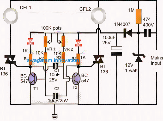
220V Alternate Lamp Flasher Circuit diagram

The circuit stage built around T1 and T2 is an ordinary astable multivibrator wherein the transistors switch alternately at a given rate as set by the values of C1, C2 and /or the values of the pots VR1 and VR2.

VR1 and VR2 can be discretely adjusted to produce different sets of flashing rates for the two lamps, or can be fixed in the middle for generating a uniform flashing pattern for the lamps.

The lamps are switched through the indicated triacs whose switching is controlled by the switching rate of the transistors, during the transistor OFF periods the traics are switched ON and vice versa, this effect is not simultaneous, rather implemented alternately for the traics giving rise to the proposed alternate flashing effect for the lamps.

Power Supply

THE CIRCUIT IS NOT ISOLATED FROM MAINS AC, AND IS THEREFORE EXTREMELY DANGEROUS TO TOUCH IN POWERED CONDITION AND WITHOUT AN INSULATED ENCLOSURE. EXTREME CAUTION IS ADVISED WHILE TESTING OR BUILDING THIS CIRCUIT.

The entire circuit is powered through a simple 12V stabilized transformerless power supply made by using a high voltage capacitor 474/400V, a rectifier diode and a 12V zener diode.

The 100uF capacitor filters the 12V stabilized half rectified output from the 1N4007 output and feeds a clean DC to the rest of the circuit for the intended operations.

You'll also like:

  • 1.  CREE XM-L T6 LED Driver Circuit – Specifications and Practical Application
  • 2.  AC Light Dimmer Circuit
  • 3.  How to Make a Simple 12 Volt LED Lantern Circuit
  • 4.  Light Emitting Diodes (LED) Explained
  • 5.  Light Dependent LED Intensity Controller Circuit
  • 6.  32V, 3 Amp LED Driver SMPS Circuit

About Swagatam

I am an electronics engineer with over 15 years of hands-on experience. I am passionate about inventing, designing electronic circuits and PCBs, and helping hobbyists bring their projects to life. That is why I founded homemade-circuits.com, a website where I share innovative circuit ideas and tutorials. Have a circuit related question? Leave a comment.... I guarantee a reply!

Previous Post: « Make this 3.3V, 5V, 9V SMPS Circuit
Next Post: Multilevel 5 Step Cascaded Sine Wave Inverter Circuit »

Reader Interactions

Comments

  1. Santhosh George says

    February 17, 2023 at 7:38 pm

    Hai I have tried the above cicrcuit but not working I have modified this same circuit using opamp I have designed entire circuit with proper zener current now it is working fine tested if anyone need they can contact in email thank you

    Reply
    • Swagatam says

      February 17, 2023 at 7:42 pm

      Op amp is absolutely not required. The above transistor circuit will 100% work if done correctly with proper understanding.

      Reply
      • Santhosh George says

        February 17, 2023 at 8:49 pm

        Thank you so much sir

        Reply
  2. CaM says

    February 8, 2023 at 12:07 pm

    Hi, i want to know what is the usage of the 2 LEDs, does the circuit still work if I delete them? thx

    Reply
    • Swagatam says

      February 8, 2023 at 12:23 pm

      LEDs are only indication of the flashing action, it is not mandatory to keep the LEDs, you can replace them with a short link.

      Reply
      • CaM says

        February 8, 2023 at 12:59 pm

        thanks a lot!

        Reply
      • CaM says

        February 10, 2023 at 10:16 am

        Hi, I made this circuit into PCB, but the 2 lamps light constantly, they do not flash, what could be the possible reason?

        Reply
        • Swagatam says

          February 10, 2023 at 12:13 pm

          Connect the LEDs in the shown position and check whether the LEDs are alternately blinking or not. If they are not blinking alternately then your transistor oscillator has problems and it might not be working correctly due to some fault.

          Reply
          • CaM says

            February 11, 2023 at 8:51 am

            thanks!

            Reply
  3. JAYANATH says

    April 21, 2018 at 7:02 pm

    sir i want to flash 3 nos ac bulbs just flash as 1,2,3 1,2,3 so on. request instructions please

    Reply
    • Swagatam says

      April 22, 2018 at 12:35 pm

      Hi Jayanth, you can use the following concept

      https://www.homemade-circuits.com/make-this-diwali-christmas-running/

      use only pin3, 2, 4, for lamp connection and ignore all the rest, and remove pin#15 connection from the ground and connect it with the pin#7

      also make sure to use a 50 ohm 1 watt resistor in series with the input capacitor 474/400V

      Reply
  4. Pradeep Kumara says

    May 14, 2017 at 4:43 am

    sir please indicate the circuit for simple on off flasher for one ac bulb

    Reply
    • Swagatam says

      May 14, 2017 at 2:31 pm

      Pradeep, you can use the same circuit that's shown above, just eliminate one of the side's triac

      Reply

Need Help? Please Leave a Comment! We value your input—Kindly keep it relevant to the above topic! Cancel reply

Your email address will not be published. Required fields are marked *

Primary Sidebar

Subscribe to New Circuit Ideas

Categories

  • Arduino Projects (87)
  • Audio and Amplifier Projects (132)
  • Automation Projects (17)
  • Automobile Electronics (101)
  • Battery Charger Circuits (83)
  • Datasheets and Components (104)
  • Electronics Theory (143)
  • Free Energy (37)
  • Games and Sports Projects (11)
  • Grid and 3-Phase (19)
  • Health related Projects (25)
  • Home Electrical Circuits (12)
  • Indicator Circuits (14)
  • Inverter Circuits (87)
  • Lamps and Lights (142)
  • Meters and Testers (69)
  • Mini Projects (46)
  • Motor Controller (64)
  • Oscillator Circuits (27)
  • Pets and Pests (15)
  • Power Supply Circuits (108)
  • Remote Control Circuits (50)
  • Security and Alarm (64)
  • Sensors and Detectors (101)
  • Solar Controller Circuits (59)
  • Temperature Controllers (42)
  • Timer and Delay Relay (49)
  • Transmitter Circuits (29)
  • Voltage Control and Protection (37)
  • Water Controller (36)

Calculators

  • Battery Back up Time Calculator
  • Capacitance Reactance Calculator
  • IC 555 Astable Calculator
  • IC 555 Monostable Calculator
  • Inductance Calculator
  • LC Resonance Calculator
  • LM317, LM338, LM396 Calculator
  • Ohm’s Law Calculator
  • Phase Angle Phase Shift Calculator
  • Power Factor (PF) Calculator
  • Reactance Calculator
  • Transistor Astable Calculator
  • Transistor base Resistor Calculator
  • Voltage Divider Calculator
  • Wire Current Calculator
  • Zener Diode Calculator
  • Filter Capacitor Calculator
  • Buck Converter Calculator
  • Boost Converter Calculator
  • Solar Panel, Inverter, Battery Calculator
  • Wire Current Calculator
  • SMPS Transformer Calculator
  • IC SG3525, SG3524 Calculator
  • Inverter LC Filter Calculator

People Also Search

555 Circuits | 741 Circuits | LM324 Circuits | LM338 Circuits | 4017 Circuits | Ultrasonic Projects | SMPS Projects | Christmas Projects | MOSFETs | Radio Circuits | Laser Circuits | PIR Projects |

Recent Comments

  • Swagatam on Real MPPT Solar Charger Circuit Using Arduino, LCD, and Manual/Auto Switch
  • Obaidullah Khan on Real MPPT Solar Charger Circuit Using Arduino, LCD, and Manual/Auto Switch
  • Swagatam on 2 Compact 12V 2 Amp SMPS Circuit for LED Driver
  • Alan Bishop on AC Motor Speed Controller Circuits using Back EMF
  • Swagatam on Real MPPT Solar Charger Circuit Using Arduino, LCD, and Manual/Auto Switch

Company

  • Privacy Policy
  • Cookie Policy
  • About Me
  • Contact
  • Disclaimer
  • Copyright
  • Videos
  • Sitemap

Social Profiles

  • Twitter
  • YouTube
  • Instagram
  • Pinterest
  • My Facebook-Page
  • Quora
  • Stack Exchange
  • Linkedin
  • © 2025 · Swagatam Innovations