This simple MOSFET controlled transformerless power supply circuit can be used for delivering a continuously variable 0 to 300V DC output and a current control from 100 mA to 1 Amp.
To protect against my high voltage research projects from going up in smoke permanently, I developed an easy circuit which is able to render a variable voltage supply of 0 to 330 Volt.
But please be cautioned, the circuit is not isolated from mains potential, and therefore can inflict a lethal shock.
The supply is short-circuit proof: the current is restricted to approximately 100mA.
WARNING: ALL THE ABOVE CIRCUITS CARRY LETHAL MAINS VOLTAGE AND THEREFORE ARE EXTREMELY DANGEROUS. IT CAN KILL ANYBODY, IF TOUCHED ANYWHERE ON THE CIRCUIT IN POWERED CONDITION. OBSERVE APPROPRIATE PRECAUTIONS TO AVOID ANY MISHAP.
Circuit Operation
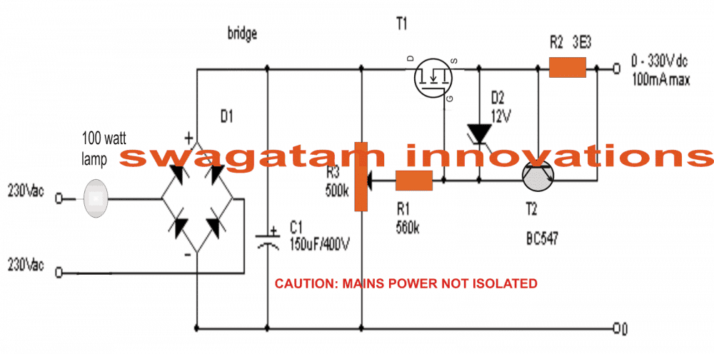
The design does not require a transformer, rather a 100 watt bulb is introduced at the input in order to provide ultimate safety in case of a short circuit or a component failure.
The mains voltage from after passing through the lamp is rectified with bridge D1 (1Amp / 500V) and C1.
T1 is configured as a source follower: the source of T1 complies with the voltage of the wiper of R3. D2 is insured to safeguard the gate of T1.
T2 and shunt resistor R2 establish the current limiter. Whenever the output current results in being excessive, T2 quickly discharges the gate of T1.
This stops the current from increasing any further. The value of R3 was basically identified experimentally; however it actually depends on the Hfe of T2 which means you may need to adjust the value of R2 appropriately.
Keep in mind T1 requires a large heatsink: in nastiest situation T1 would probably disperse 330V x 100mA = 33Watt!
You may try mosfets such as a BUZ 326 (400V/10.5Amp) or you may likewise use an IRF740 (400V/10Amp).
The output impedance of the power supply varies according to the beta of T1, therefore the bigger the MOSFET, the lesser the output impedance!
Circuit Diagram
UPDATE:
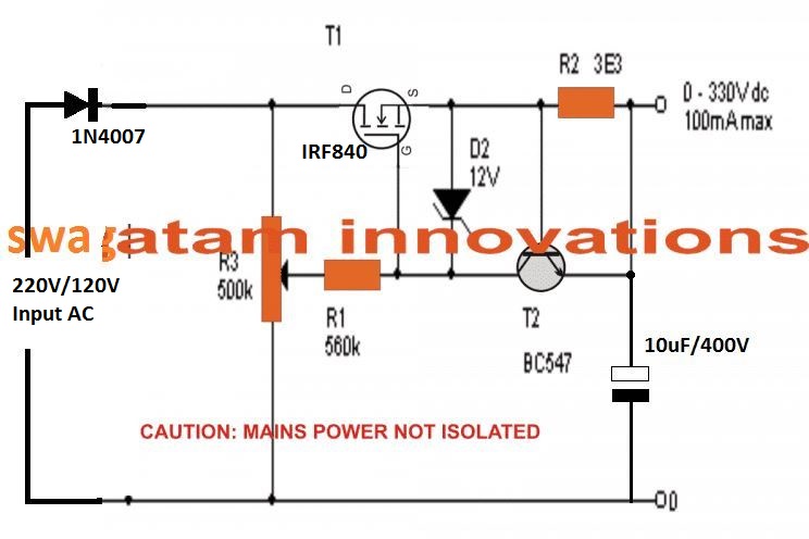
The above design could be much simplified as indicated in the following diagram. The bridge rectifier has been eliminated which drastically reduces the stress level on the MOSFET.
However, the ripple generated due to a half wave rectification may be significantly higher.
The output 10uF filter capacitor helps to reduce this to some extent. The value of this capacitor could be increased to higher levels for improving the DC quality.
The input series lamp can be added, although this may not be required due to the presence of the current control stage in the design. However, for better safety a fuse may be added in series with the input line.
The output load specification must not exceed 100 ma
Video Proof:
This power supply can be used to obtain a regulated power output, variable right from zero to 300 volts maximum. All the devices should be mounted on heatsinks.
Working Principle
The circuit regulates the output voltage using an IRF840 MOSFET (T1) as the main regulating element.
The 500k potentiometer (R3) controls the gate voltage of the IRF840 thus varying the output voltage.
The output current is controlled via the current-sensing resistor R2. When the voltage drop across R2 exceeds the base-emitter voltage of the BC547 transistor (T2 typically 0.6V to 0.7V) then T2 turns ON and reduces the gate voltage of T1 limiting the current.
D2 (12V Zener diode) ensures that the voltage of the IRF840 between its gate and source does not exceed 12V.
Key Parameters
- Vout: Adjustable output voltage (0–300V DC)
- Iout: Maximum output current (A)
- R2: Current sensing resistor (ohms)
- R3: Potentiometer for voltage control (ohms)
- Vin: Input voltage (rectified 220V AC ≈ 310V DC)
Formulas
- Output Voltage Control
The gate voltage of T1 is determined by the setting of the 500k potentiometer (R3). The output voltage is approximately proportional to the gate voltage of T1.
Vout ≈ Vgs(T1) - Vds(on)
- Where:
- Vgs(T1) = Gate-to-source voltage of T1
- Vds(on) = Drain-to-source voltage when T1 conducts (small value around few volts)
- Current Limiting (Iout)
The current limiting is handled by the sensing resistor R2. The voltage drop across R2 is compared with the base-emitter voltage of T2 (Vbe approximately 0.6V–0.7V). When the voltage drop across R2 exceeds Vbe, T2 turns ON and reduces the gate voltage of T1, thereby limiting the current.
Iout = Vbe / R2
- Where:
- Iout = Maximum output current (A)
- Vbe = Base-emitter voltage of T2 (typically 0.6V–0.7V)
- R2 = Current sensing resistor (ohms)
- Power Dissipation in R2
The sensing resistor R2 must dissipate power proportional to the output current:
P(R2) = Iout2 * R2
- Where:
- P(R2) = Power dissipated in R2 (W)
Choose a resistor with a power rating higher than P(R2) for safe operation.
- MOSFET Power Dissipation
The IRF840 MOSFET dissipates power due to the voltage drop across it and the output current:
P(T1) = (Vin - Vout) * Iout
- Where:
- P(T1) = Power dissipated in T1 (W)
- Vin = Input voltage (DC, ≈310V for rectified 220V AC)
- Vout = Output voltage (adjustable)
- Iout = Output current (A)
Ensure T1 has adequate heat sinking to handle the calculated power dissipation.
Example Calculations
Let us Assume:
Vin = 310V DC peak rectified from 220V AC.
Vout = 300V DC
Iout = 0.5A (desired maximum current)
Vbe = 0.6V
Step 1: Calculate R2 (Current Sensing Resistor)
R2 = Vbe / Iout = 0.6 / 0.5 = 1.2 ohms
Step 2: Power Dissipation in R2
P(R2) = Iout2 * R2 = 0.52 * 1.2 = 0.3W
Choose a resistor with at least a 0.5W rating for safety.
Step 3: Power Dissipation in T1 (IRF840)
At maximum output:
P(T1) = (Vin - Vout) * Iout
= (310 - 300) * 0.5
= 10 * 0.5 = 5W
At lower output voltages the power dissipation in T1 will increase so choose the heat sink to handle the worst-case scenario.
A Failproof 300V Variable Power Supply Design
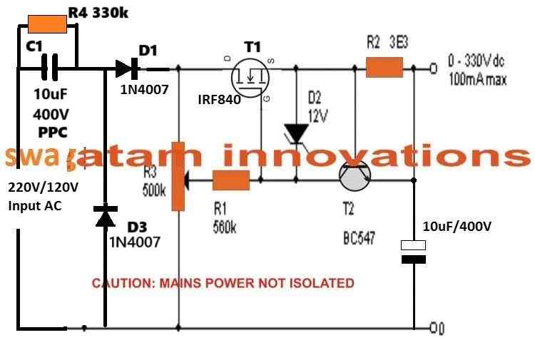
To make the above 300V adjustable power supply completely safe and failproof, you can modify it by adding an input current limiting capacitor, as shown in the following diagram.
However, please remember that the circuit is safe and failproof only for the MOSFET, but it still carries a floating 300V AC, which can be lethal for any human if the circuit is touched in open and powered condition.
Using a Combination of BJT and Mosfets
Circuit Operation
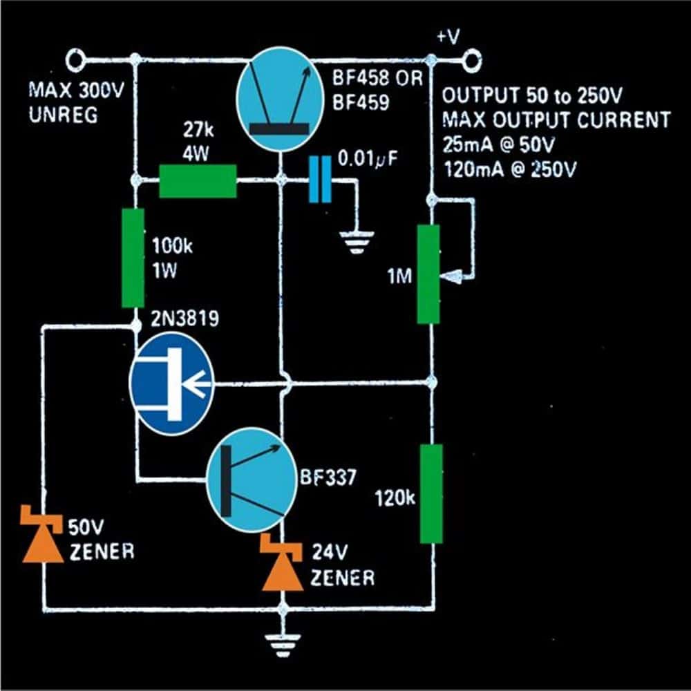
The next transformerless 0-300V variable power supply circuit diagram can be understood with the following points:
As can be seen in the figure, a high voltage transistor BF458 is used as the main load handling device.
Its base bias is controlled by another high voltage transistor BF337 whose emitter is clamped to a stable 24 volts.
An FET is used for selecting the base current of the transistor BF337 via a pot of 1M.
This setting adjusts the base current for the BF337 which in turn restricts the main transistor BF458s voltage and current flow to the output.
The input to the circuit may be derived directly from the mains AC after proper rectification and filtration using a bridge network and a 10u/400V capacitor.
The entire circuit is extremely dangerous to touch, due care should be maintained while making and testing this circuit.
Converting 80V DC to 5V DC Stabilized Output
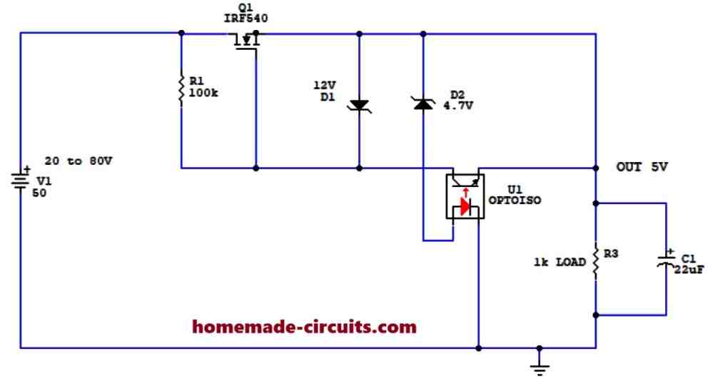
The above explained 300V MOSFET regulator circuit was successfully modified by Mr. Luigi to convert a varying input between 20V and 80V DC into a stabilized 5V DC output, using an opto-coupler feedback, as shown in the following figure. I am grateful to Mr. Luigi for contributing this design to this website.



Questions & Answers
Thank you Mr. Majumder for publishing this ckt. However I require a perfect ckt. for charging my 2X1.5 V chargeable batteries i.e. a 3V charger directy from 220V AC main supply, those are generally supplied with chinese make re-chargeable torches (easily available in the local market). My two sets has been damaged & I am unable to use them.
You can use your cell phone charger for charging the 3V batteries by adding 4nos diodes in series with the positive line. The diodes can be 1N4007 type.
Hello sir please help me!!!
I have 220v to 400v 2A stepup transformer, actually according to various condition I want 0v DC to 400v DC using microcontroller’s PWM technique not by any potentiometer resistor, I am expert in programming only but not in power electronics. I need your help….my mobile no. is 8983378973.
Hello Mudassir,
what help do you exactly need in power electronics, please specify? With 400V PWM the peak will be always 400V which can be dangerous for many appliances.
Actually according to various conditions I need DC voltages like 25V DC, 50V DC, 75V DC, 100V DC……………375V DC and 400V DC. I know that , at various T-ON and T-OFF timings of the PWM we can generate various output voltages, but i dont have any MOSFET circuit to do so.
I request you please provide me a circuit diagram with suitable MOSFET rating so that i directly give output of PWM to the circuit to generate the voltages. As i have said that i already have stepup transformer (220v to 400v)
You can use the set up explained in the following article:
https://www.homemade-circuits.com/arduino-full-bridge-h-bridge-sinewave-inverter-circuit/
Repace the Arduino with your PWM input, and make sure to connect the MOSFet drain/source to the 400V DC supply.
The PNP MOSFET will need to be replaced with a 400V PNP MPSFeTs,and the n mosfets can be FDD6N50TM-F085
The PNP mosfet may get significantly hot so make sure to mount them on proper heatsinks
Hi!
Thanks for sharing. I'm actually designing a similar circuit but with SCRs to improve efficiency, did you think about doing one like that?
Kind regards,
Francisco
Hi, yes I have a SCR design using a zero crossing detector stage, but I am not very sure if it would be entirely safe.
The above design looks more convincing to me.
sir plz give modification for high amp like 50amp at 60v thankx in advance.
Nitin, connect more mosfets in parallel with the existing one, and calculate R2 accordingly…
Dear Sir please tell me how can I know about the functions of different IC's….
Dear Arpan,
check their datasheets.
Hello sir swagatam please tell me how make Stabiliser AC
hello joseph, you can try the following circuit:
https://www.homemade-circuits.com/2011/12/how-to-make-small-homemade-automatic.html
more example links can be found at the bottom of the article
thank you sir swagatam, i will try
Thanks Sir.Sir please suggest me a book where I can found the datasheet of different ICs
Arapan, the internet is the best source for learning the datasheets, you can try googling them online.
hi Swagatam 🙂
I want to ask.
1. if the input should be given 100watt bulb
2. if the circuit is safe to touch the output.
3. and for how many watts the resistor wear.
Hi Muhamad,
1) yes 100 watt is required for safeguarding the mosfet
2) No the circuit is extremely dangerous to touch
3)R2 is 2 watt rest all are 1/4 watt
Hi sir I want to make a variable power supply for 1Amp load.
My purpose is to test relays and adjusting 555based, Opamp based circuit….
Please sir help me…
bhanu, you can use a LM317 circuit as shown in the first diagram here:
https://www.homemade-circuits.com/2011/12/how-to-build-simplest-variable-power.html
use 10k instead of 5k for the pot
input can be anything from 5V to 30V
Thanks sir let me try………but I have an diagram how can I send it to you in which e-mail id…
you can upload it to any free image hosting site online and provide the link to me here, i'll check it out
Can i get a circuit like this that can produce dual polarity voltages for various amplifiers from probably 0-100v at about 3 or more amps, the supply in my country is 110v
you can try the following circuit:
https://www.homemade-circuits.com/2013/06/0-300v-variable-voltage-current.html#uds-search-results
use TIP35/TIP36 instead of 2N3055/2955 in the diagram for getting a 0-100V range
…I do not have a trasformerless design at the moment…
I would need something to provide -70, +70 and ground
with this circuit i was wondering if I use the ground from the supply along with each output if that would work.
I don't think that would work
ok then so you haven't desinged any circuit like that +70 -70 & Gnd
sorry, I think I gave you the wrong link, here's the one I wanted you to see:
https://www.homemade-circuits.com/2014/07/0-to-50v-0-to10amp-variable-dual-power.html
but it will require a transformer.
you can do it by altering the R2 value.
R2 = 0.6/.3 = 2 ohms, is a good value for getting 300mA
Hello, and thanks for the diagram. Have tested it and the setup continues to burn the irf740 as soon as I come over about 250DC primary. Has cooling, and tested with bulb at about ½ wattage. Have tried with less zener, but even 10v burns it. What could be the reason?
Hello, the circuit won't activate until a load is connected at the output, if it's burning without a load then something could be seriously wrong with connections or the device, make sure that the fet "source" is towards the load.
and remove C1 initially and check the response without it
also you can try connecting the zener across the gate and bridge (-) of the supply.
if you have excluded the current limiting stage then initially try a resistive load with relatively high resistance such as a 40 watt bulb at the load side or a 25 watt soldering iron etc.
In this situation the input 100 watt bulb can be eliminated.
Please sir, what modifications can i make in the circuit above in order to get a regulated 12v, 300mA at the output? And i don't need the light bulb at the input.
Jideofor, I cannot suggest much regarding this circuit because it is not designed by me and it can be dangerous if anything goes wrong, especially because it is not isolated from the mains in any manner…
it's better to go for a capacitive power supply
Hi Mr. Majumdar,
Is this able to used for electron tube amplifier, without any hum?.
Thanks so much.
Hi Ronald, hum will depend on the filter capacitor value, if it is properly optimized then the hum can be controlled to the desired limits.
Hi dear Swagatam
i need a transformless power supply for my leds which change 230 v ac to 0-35 v or more
but please simple and without transformer
regards,
Ali, you did not mention the current requirement….?
2-5 amps
but please simple
that's very high, you will have to opt for an SMPS version, capacitive type may not be recommended.
Thankss swagatam
Ok,below 1 amp i can choose?
Ali, you can try the following concept
https://www.homemade-circuits.com/2016/07/scr-shunt-for-protecting-capacitive-led.html
but make sure the SCR is rated above 2 amps
and change the zener diode with a 35V, 1 watt
Hi
I'm looking to make a 430V 150ma supply for a tube amplifier. If I use a 350V transformer to supply the input voltage, increase the voltage on C1 to 600V and use a higher rated MOSFET, should the above layout work? What would you recommend as a suitable MOSFET? Any issues that you can see in an audio application?
Hi, yes according to me it should work….
Thanks. I'll give it a go.
Please sir can u elaborate more on how to calculate the value of R2 because if i multiple the value of R2 being 3E3 by 100mA is not giving me the 330v. And in one of the comments i read u said for 300mA R2 will be 2ohms u get by dividing 0.6/0.3 i want to know the 0.6 please can u give me steps on how 2ohms is gotten
Thanks and best Regards
Faith, use the following formula for setting up the resistor
R2= 12/current Limit
for 100mA, this becomes
R2 = 12/100 = 0.12 ohms
correction:
R2 = 12/0.1 = 120 ohms
Please the 12v is it as a result of 12v zener diode please how come the 12v and why not use 330v which is the required output voltage
yes it is, but the main reason is that by grounding 12V level the mosfet will be completely shut off…
Hi Sir ..Your circuit ideas are awesome.
I am designing a variable dual power supply circuit with high current output .. I have a 300 W transformer. I was initially thinking of making the circuit with LM317 and LM337.. but it is very difficult to get LM337 in our place. So I have designed the circuit with 7805 and 7905 Ics. By putting them in dual mode with the ground as common I got +5V 0 -5V dual power.. By connecting 2 pots between the Battery ground and the Ground pins of 7805 ( pin#2 ) and 7905 ( pin#1 ) I could tweek the output voltage from 5V to the full 15V range which was exactly my requirement.. The circuit is successfull in delivering the voltage range.. But the real problem happens next I am not able to take enough current from the output. I cant run high current loads with it. To compensate that I have used 2 to 4 no.s of TIP3055 Ics after 7805 regulator and there was improvement in the current. But not completely.. Now I need the help of you to design the current amplifier section at the output of the negative voltage regulator Ic ( 7905 ). I have several 2N3055 NPN transistors and MJE2955 PNP Transistors with me.. please help in this problem.. I have sent you an email comprising the designed circuit
Hi RT,
Your 2N3055 connections are correct and they should be able to deliver high current, but make sure to add a low value (may be a 22 ohm2 watt) resistor with the base of each transistor, otherwise they may get damaged if the load is bigger.
hi sir swagatam is this circuit could be use in testing led strip?
or how to modify this circuit for the purpose of testing led back lights strip without shock
Hi Elmar, shock cannot be avoided in this design, it’s better to use an SMPS based power supply instead of this one if shock is a concern
sir can i ask a favor ? could you make for me a circuit intended for testing a led strip for led tv back lights? i made this circuit above i used a 1:1 ratio transformer it works well even in a single beads with out damaging it but my fear is the electric shock.
elmar, if you are using a 1:1 trafo then shock is already controlled to a great extent, make sure the current rating of the secondary is less the 10ma, and use a large filter capacitor after the bridge,
thank you very much sir for your kindness.
you are welcome!
Hello sir ,
I need to make a circuit which switchover automatically between 11.1v 8800mah li ion battery and smps 12v 2amp circuit.At the load side I have used stepper motor ,TFT graphic lcd and wifi unit which is powered by smps supply. Is it possible to charge a battery with this smps supply and make switching to battery supply in the absense of smps supply.Charger circuit is also required.I am new to electronics please help me to find out charger circuit+auto switch circuit.
Hello Sham, you can try the second circuit from the following article
https://www.homemade-circuits.com/2013/04/automatic-micro-ups-circuit.html
please adjust the opamp preset through proper understanding and thinking, otherwise you will keep struggling with it.
The idea is simple.
pin#3 of the opamp is the battery voltage sensor.
when the voltage on this pin#3 goes higher than the pin#2, pin#6 switches to the supply level and vice versa, since pin#2 is fixed at 4.7V implies that as soon as pin#3 voltage becomes higher than 4.7V, pin#6 instantly becomes high, switching OFF the PNP transistor
Can we modify it to have adjustable current too. Where do i need to put a current limit potentiometer. Using direct potentiometer isn’t suitable as i require 3 to 5 amps power.
you can modify the R2 section with a rotary selector switch and attach the desired number of resistors with it, and then you can select one of those for achieving the required current control limit
Thanks a lot for this circuit? Mr swagatam, i can apply this in my led strip wit 72 leds, each 3 led will light in 12 volts, in total series of led will consume of 208 volts. i ask one more question is this safe for my back light led tv as a subtitute in broaken inverter? thanks a lot for your reply, GOD bless!
Thank you Armand, I am sorry since this design is not mine I cannot suggest anything with confidence. Although others have built it successfully I still wouldn’t want to risk anything by suggesting on assumptions.
hello sir may i ask if u have a circuit to control the speed of a dc motor 180vdc input 1.5 hp. thanks
Hi Ralph, you can adapt the following concept and easily use it for your specific application
https://www.homemade-circuits.com/make-this-pwm-based-dc-motor-speed/
Hi Eng. Swagatam,
Thanks for the numerous circuits and electronic designs you have freely placed at the public domain for our viewing and experimenting with.
I need a 19v to 19.2v transformerless DC power supply to operate a cordless circular saw whose battery packs are very dead. I hope you can help with a circuit design. Many thanks
Thanks Danny, could you please tell me the current requirement for the load, in amps.
Glad to receive a fast response from you.
Unfortunately the cordless saw does not carry any of the requested information on neither the device itself nor the accessories like the battery pack nor the charger set. I saw nothing too in the manual.
Here are links to the manuals: https://www.alltradetools.com/pdfs/new/archive/Kawasaki-19.2V-3-to-5-Hr-Battery_840638_eng.pdf
https://usermanual.wiki/Kawasaki/Kawasaki691191UsersManual219633.2052279797/view
However I want to open one of the two battery packs to see the voltage and amps of each battery as well the number of batteries in each pack. I welcome any advice from you sir. Many thanks. Danny
Surprisingly the linked articles also do not have any reference to the current requirement of the unit. However I assume it to be no less than 10 amps or even higher. Your battery specs might help us to get the required information.
Yes, I from what I saw in the battery pack embossed on each battery may be of help.
Kindly peruse these information:
Number of Batteries in a pack: 16 pieces of Battery
Ampere of each Battery: 1300mAh
Voltage of each Battery: 1.2 volts
Voltage of battery pack (total voltage used by the cordless saw): 19.2v
Eng. I hope these current information may churn out something good.
Many thanks for your time and patience. Danny
OK, it means a 1 amp smps would be enough, although i find it strange how a 20 watt supply can power a powerful saw unit?? You can try the second design from this article:
https://www.homemade-circuits.com/how-to-make-simple-12-v-1-amp-switch/
to get 19V you can modify the output winding to 20 turns, and change the zener diode to 20V zener.
Yes Eng. but my issue is not a charger problem. The power tool came with 2 battery packs but are all dead. They are very expensive to replace so I have decided to convert it from a cordless to a corded tool. That is I want to use an AC – DC power supply instead of a battery pack. So what I need is a circuit that can provide the 19.2v (20v) and the accompanying respective wattage which I guess is about 400w. Many thanks
Sorry Danny, I got lost, I mistakenly imagined that the batteries needed to be charged. I do not have a 20amp SMPS circuit , and even if I had I wouldn’t have recommended it due to its complexity. The easiest option is to get a 14V 20 amp iron core transformer, and rectify its output using 50 amp bridge rectifier and a 2200uF/50V filter capacitor. This would perfectly take care of your 400 watt saw and drive it smoothly without any issues, although the size of this trafo could be too large.
Many thanks Eng. Swagatam for your help and advice.
You are welcome Danny!
Hello Eng. Swagatam,
Find below the manner I calculated the wattage:
Given:
Number of Batteries in a pack: 16 pieces of Battery
Ampere of each Battery: 1300mAh
Voltage of each Battery: 1.2 volts
Then:
Voltage of battery pack (total voltage used by the cordless saw): 19.2v=16 pieces of Battery x 1.2 volts (Voltage of each Battery)
Amperage of the tool (total):20.800 = Ampere of each Battery: 1300mAh x 16 (Number of Batteries in a pack)
Wattage of the tool (total): 399.36 = total voltage: 19.2v x 20.800amps (Amperage of the tool (total))
My Summary:
Voltage: 19.2
Amperage: 20.800amps
Wattage: 399.36watts
Eng. as a matter of fact I am amateur in electronics. I started it as a hobby so please I stand to be corrected on the above presentation.
In case it is correct, kindly modify the suggested circuit to output at least 400watts/20v power. If there are any mistakes please tutor me on it.
Now concerning the winding of the transformer, is it possible to recommend already made one for me to purchase. Getting the items required for the transformer to DIY is posing a challenge. Many thanks. Danny
Thanks Danny,
When supply sources are joined in series, their voltages will add up, but current specs won’t.
So in your case the total voltage will be 19.2V but the current will be only 1300mAh.
You cannot draw more than 1.3 amps (max) from this series battery set up for your saw machine.
And therefore a 1 amp current would be more than enough to charge this battery series, without issues.
…yes you can easily buy one from any online store, or more simply you can do it with a transformer based design, as shown in this article:
https://www.homemade-circuits.com/how-to-make-current-controlled-12-volt/
Dear Mr. Swagatam,
I need a trnsformerless power supply with dual ouput. The first output is to drive leds (50-250/300V, 5-20mA), and the second output is for supply the controller circuit (microcontroller/arduino) (5V stable, 7805).
Please give me the schematic circuit or link that meets to its need.
Thanks
Hi Izul,
you can try this
remember it is not isolated from mains and can be fatal to touch when powered.
Thank you Sir.
Dear
I HAVE A UNIVERSAL MOTOR VACUUM CLEANER MOTOR 2000 WAT I WANT TO OPERATE IT ON DC VOLTAGE IS THIS CIRCUIT ABLE TO OPERATE IT
PLEASE ADVICE ME
Hello, if the motor is a DC motor then it will work with this circuit, but if it’s an AC motor then it won’t.
Hi Sir,
SMPS circuit is design with high frequency transformer and KA5M0***R fet for spindle motor drives but the problem is there so much power dissipation across FET so what step should be taken to resolve that problem.
best regards
H Sam, a power device will start getting too hot if the load exceeds its optimal ratings. Make sure to use an FET whose current and voltage ratings are twice that of the load or the motor rating
Good day,
I really need to lower the mains voltage (230Vac) to 100V but i don’t want to use this power supply as it is now because it’s current is limited to 100mA and i need about 40A. If i put more transistors in parallel and of higher current ratings and remove R2 and T2 i’am sure the current will go higher, right sir?
Yes that’s right, but the output will not be an AC, it will be DC
Good day sir,
I tried this schematic and as i said i used two paralleled FDL100N50F mosfets and a 5W 12V zenner. This is the problem: when i connect a 2000W load such as a resistor to it, the voltage immediately rises to 187V and won’t let me adjust it from the potentiometer. What can i do to be able to adjust the voltage?
Thank you,
Good day Razvan, as you can see in the video, it works smoothly for a resistive load, so it should work for your application also, unless something is incorrect in your design.
I would recommend testing it with a 220V bulb using a single MOSFET, to check if there’s anything wrong in the configuration
Sir please suggest me a circuit for 0-50v 0-1amp regulated variable power supply
Hi Arun, you can try this circuit:
https://www.homemade-circuits.com/0-60v-lm317-variable-power-supply/
Good day sir, Can I use these curcuit to supply plate voltage of 250vdc at 150mA? If I parallel two output regulator will it be able to supply plate voltage for my vacuum tube project? Thanks
Hi Cornelio, Yes surely you can do it, but the MOSFET will not need any change. You can either do it by modifying the R2 value, or by replacing the lamp with a 3uF/400V capacitor. Then you can remove T2 and R2 entirely
sir, the circuit which is shown in image is different then what is shown in video. As one capacitor, one transistor, one zener and two resistance is used but in video 3 zener one resistance is used. please help me i want this variable power supply from 0-150 v for gel electrophoresis purpose.
Pawan, in the video 4nos of 3V zeners are used in series to make a 12V zener. And the current control stage is not used…the basic voltage control set up is the same as shown in the diagram.
Plz give me the circuit diagram of AC 0-300v/.500ma transformerless variable power supply .
use a light dimmer circuit:
https://www.homemade-circuits.com/how-to-make-simplest-triac-flasher/