Contributor Credit: This conceptual proposal and the structural framework of the Earth Torque Generator (ETG) have been developed and contributed by Mr. Ike Higgins, continuing his ongoing dedication to introducing public-domain concepts for environmental restoration and planetary healing.
Introduction
In an effort to continue my quest to get new ideas for technology that will help us help the biosphere to heal from the mistakes we’ve made and subjected the environment to in recent times, I have initiated a process to guide my effort. What we need are ideas that present a “chain of physics” that is valid, and produces a result that provides a needed benefit to the biosphere. It is only the chain of physics that is the goal herein. Practicality, application, engineerability, cost, schedule, or other details are NOT a consideration here. Only the new idea that presents a valid chain of physics. This therefore is about a concept, not a design.
Core Philosophy: Nature In, Electricity Out
The input to the physics chain idea must come free from Nature. The output I’ve selected to chase is electricity. Nature in, electricity out. A windmill is a good example. This is the outcome that has been given to the public domain with my publication of “The Higgins Engine” (Gravity in, electricity out). That presentation goes in to a little more detail about the overall effort so I won’t repeat it here. But basically, if we have enough electricity to power the new machines we need, those machines can clean the atmosphere (like extracting CO2), or extract heat energy from ocean currents (then use it productively like with a Stirling Engine), or a plethora of other possibilities to clean up our mess and then hope Nature can take care of the rest. Those machines are not the purpose of this submission. Only the valid chain of physics idea. With enough new ideas for the physics, someone somewhere could take some of this and some of that and come up with the needed machines.
Presentation Methodology
To this end, I will be presenting these ideas using common language, not scientific physics and mathematics that are only understandable by professionals. After the general description I will address some more detailed physics (for those that require such a thing). Real people have plenty of ideas that are valid. Without the need for a degree in physics. With that, I present my latest idea. Remember, this is a concept of valid physics. That is all.
Introducing the E T Generator (ETG)
I’m going to present this by going through the functionality, before I disclose the nature of the clean input from Nature. It is that input that might cause the most tis-tisking. But in concept, the physics are valid. Introducing: The E T Generator (ETG).
System Boundaries and Basic Architecture
Let me declare boundaries for this presentation. The technology to produce electricity is well known and quite advanced. I won’t be going in to the design of an electric generator. But I will be simplifying the dialog around that technology by only referring to a Rotor and a Stator. A spinning shaft with magnets attached is a (very) simplistic explanation of a Rotor. A length of wire coiled around an open center is a (very) simplistic explanation of a Stator. By positioning the spinning Rotor through the center of the coiled wire Stator, electricity on the wire will be produced. The E T Generator is just that. A spinning Rotor in the center of a Stator. So, all we need from Nature is to spin the Rotor. Again, I’ll explain the input from Nature later.
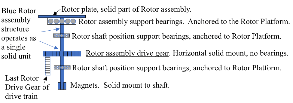
The Three Core Mechanical Assemblies
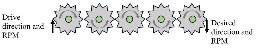
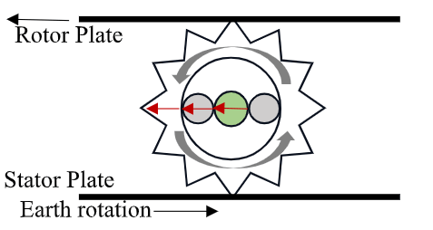
There are three assemblies (of physical phenomenon) that will be described. Two “gear plates” (assemblies #1 and #3) that will used as equipment platforms and as mechanical gears. Assembly #2 includes three free spinning gears in between plates #1 and #3. It is the specifics about the direction of spin for each assembly, the torque needed to spin each assembly, and the specific architectural positioning for the interface of the three assemblies that provide the valid chain of physics. Gear Plate #1 will now be referred to as the Stator platform. Gear Plate #3 will be referred to as the Rotor platform. Assembly #2 will be referred to as the Drive Interface Gears. All three assemblies are “anchored” independently from each other. The anchor refers to the shaft holding the wheel bearings in the center of a gear. Gears spin around the wheel bearings. Following is a diagram of the physics concept (not design) for the arrangement of the three assemblies. Sorry the gear points don’t align but I’m drawing in Word, so cut me some slack. You get the idea.
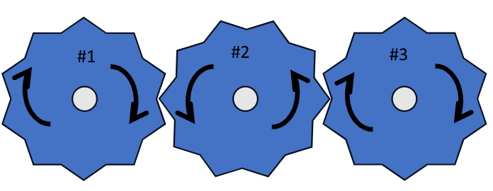
If #1 spins clockwise, #2 spins counter-clockwise, causing #3 to spin clockwise. This diagram shows the workings if all three were on a flat plane. In this configuration all three could be anchored to the same structure with the gears spinning around the wheel bearings in the middle of each. It is the anchor that is the key. With a different architecture, anchors for the three assemblies are separate and independent, but the rotational physics is the same as the diagram above.
Platform Placement and Synchronization
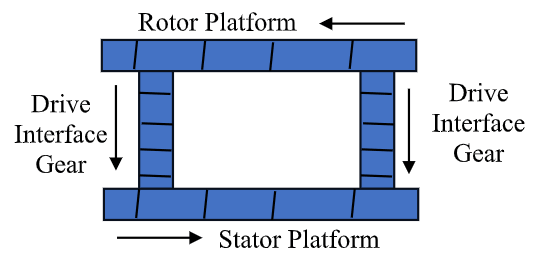
Plate #1, the Stator Platform, has all the electronics necessary for the Stator hardware. That hardware is mounted on that platform, and therefore stationary with respect to that plate. Plate #3, the Rotor Platform, has all the electronics necessary for the Rotor hardware mounted on it. Again, all that hardware is stationary with respect to that plate. Assembly #2, the Drive Interface Gears, are anchored to an independent structure (not shown). The gears spin in accordance with the position of that anchor.
When the three assemblies are stacked, the Rotor and the Stator are rotating in synchronized opposition. Rotating in opposite directions. The arrows in the diagram below show the direction of travel looking from a single point of view (front view). Only two Drive Interface Gears are shown to demonstrate the physics concept. A sturdy, vertical structure to anchor a tripod of drive gears, and the strength of the gear teeth interface to #1 and #3, would provide a structural foundation to hold up the free-floating Rotor platform during operation.
This is the basic mechanical physics for the ETG. Now the functionality of the ETG.
Rotational Dynamics and Relative Motion
The only way this architecture can work is if there is a difference in movement between the parts. For gears to spin around a shaft, that differential is required. Directional forces decide that differential in movement. The shaft holding the wheel bearings, in position, is stable. The gears spinning around the wheel bearings are mobile in angular velocity. That relationship is maintained even if the entire structure is moving. But only the direct one-on-one relationship between any two units is a consideration.
If you are standing on the Stator Plate, all the equipment is stationary with respect to your position. But look up and the Rotor Plate is rotating above you. If you are standing on the Rotor Plate, you are stationary with all of that equipment. But look down, the Stator Plate is rotating under you. If you are standing away from both, both are rotating. It is that relative relationship, depending on your point of view, that is to be exploited for functionality.
The Anchor Principle and Grounding
This is where the anchor for the Drive Gears becomes important. If the Stator Plate is rotating, the only way the drive gears can turn is if their anchor has a differential in angular velocity with the Stator Plate. If the drive gear shafts holding the wheel bearings were anchored on the stator plate, nothing would turn. They would be stationary in relation to each other. So the drive gear anchor shafts have to stay in one spot, while the Stator Plate spins. Here it comes.
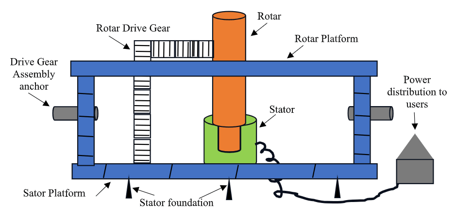
The Stator Plate is solidly mounted to ground. There is not a center shaft or wheel bearings in the center of the plate for it to spin around. If you are standing beside it, it is sitting still. That requires that the anchor for the Drive Gears has to be moving to create the angular velocity differential with the stator plate. In the ETG, the foundational structure holding the shaft, that holds the wheel bearings for the drive gears, is travelling around the circle independent of the stator plate. That differential causes the drive gears to spin which causes the Rotor plate to spin. Here it is.
Unveiling the Source: Earth Torque Generation
The Stator Plate is foundationally built on the ground. Deep footings, foundation structure, the whole bit. It is a solid platform with structures and infrastructure built on it. There are wires coming out from under the platform to a power plant building for final distribution of electricity. Standing on the ground anywhere around there you see permanent structures. On top of the horizontal plate, at the outer edge, are slots for gear teeth to fit in. If you are now looking down from the North Pole (Polaris), you would see the Stator Plate rotating at one Revolution per day (1 RPD). This is it. The Stator Plate is centered over either the North or South Pole. The shaft, around which the Stator Plate spins, is literally the axis of the earth. [now don’t go there. Remember what is not under consideration at this time.] ETG stands for Earth Torque Generator. The rotation of the earth in, electricity out. The chain of physics is valid.
If you have a plate centered on the pole (North for this discussion) it will rotate counter clockwise with the earth. Only the strength of the structure you build will limit the output of the ETG. The torque and rpm of the rotating earth is the Nature input to the ETG system. Nature in, electricity out.
Torque vs. RPM: Accessing Limitless Energy
To jump ahead, the energy needed to drive a shaft at some RPM with enough torque to overcome the load (electromagnetic, weight, friction, etc.) on the shaft can be described by those two parameters. Torque and RPM. The design of an electromagnetic generator comes down to the level of a relational combination of Torque and RPM input power. When engineering, those two items can be “traded off” in the quest for the sweet spot energy output. Less torque, more rpm. Less rpm, more torque. The generator is designed for a specific rpm/torque input combo. Now consider that you have the torque of the rotating earth, with very low rpm. That means that virtually any rpm is mechanically available, limited only by the robustness of the structure. It just depends on how much output energy you want your design to provide. Relatively speaking (human versus nature) you have limitless torque to play with. How does a gigawatt/hour generator sound?
Rotor Platform Dynamics and Load Paths
Back to the ETG. The Stator platform being described, the Rotor platform now needs some detail. Remember that this platform is free floating on top of the drive gears. And is rotating at 1 Revolution Per Day in a clockwise direction. All equipment needed to spin the Rotor is built on this platform. The Rotor drive shaft is designed to extend down through the open space of the drive gear area in to the open space at the center of the stator circuitry. The interface will be the electromagnetic field created between the two units. This is an electromagnetic load on the Rotor drive shaft and is realized by a torque force resistance to turning (spinning) in the solid environment of the shaft. The generator load level determines the desired output.
The gearing mechanism, built on the Rotor Platform, that actually turns the Rotor is powered from the Stator platform. Independent from the Drive Gear Assembly rotation power. The input end of that Rotor drive gearing is extended independently to the Stator Platform and is “plugged in” to the gear teeth slots on that platform. These gears are anchored (shaft with wheel bearings) on the Rotor Platform. This chain of gears is the load path that the electromatic resistance on the Rotor is handled by the torque of the earth.
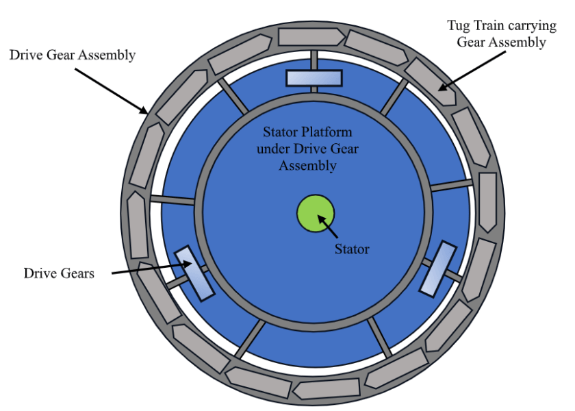
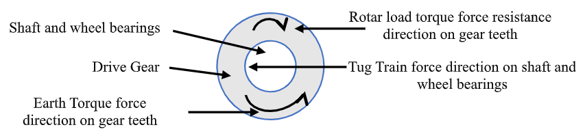
The Drive Gear Assembly and the "Tug-Train" Concept
Now the Drive Gear Assembly. The assembly is a solid structure that provides an independent platform for anchors (shafts for wheel bearings). The entire assembly is mounted on a circular foundation that is mobile. As a mental visual, think about a freight train with a couple of locomotives pulling a mile of freight cars down the track. The Drive Gear Assembly track is a circle around the stacked platforms. The freight train is on that round track. The “freight cars” are carrying the Drive Gear Assembly structure in totality. This results in the entire Drive Gear Assembly revolving clockwise.
Velocity of the round train, called the Tug-Train, is 1 Revolution Per Day, in the opposite direction of the rotation of the earth. Because of the opposing rotation directions of the Stator and Rotor Platforms, the differential between the two is 2 RPD. Although there is no “day” for the Drive Gear Assembly. If you were sitting on the train and looking at the sky, it would never change.
The stars are stationary in the sky. There would be slow movement of the planets, the moon, and any asteroids that happen to be flying by. But the Milky Way would be stationary, for you. A “stationary” shaft holding the wheel bearings for the drive gears. This lets the Stator Platform turn with the earth, the drive gears spin, and the Rotor Platform freely spinning on top.
Energy Net-Gain and Parasitic Load Handling
The question arises regarding the force (energy) needed to operate the Tug Train. The forces acting against the forward motion of the Tug Train are a combination from several origins. However, the directions of the forces are very important. The Tug Train is pushing horizontally, and therefore being felt on the shaft holding the wheel bearings in the center of the Drive Gears. The shafts push on one side only of the inside of the wheel bearings. The drive gears are feeling opposing forces on the outer edge of the gears, through the gear teeth. Due to the solid structure of the gears, these forces remain “mostly” around the gear to the teeth on the other side, not pointed in to the center on the shaft. This outer edge is the load path for the electromagnetic resistance coming from the Rotor. The result is that the Tug Train only has to overcome the forces of the weight of the Rotor Platform, the friction of the wheel bearings, and “some” electromagnetically created torque resisting movement. This combination is (untested so only “should be”) much less than the torque force to be overcome from the Rotor. The diagram below shows the direction of the force vectors.
The Tug Train will require a significant amount of energy to operate. Think electric locomotives. However, the anticipated output from the generator is much more than “significant”. Probably by orders of magnitude. Undoubtedly more than what is required to power the Tug Train. Therefore, you guessed it, some of the output is routed back to power the Tug Train. It may not be much of a hit to the gigawatt hours output of the Earth Torque Generator. The function of the Tug Train and the function of spinning the Rotor are two independent functions. Requiring the separation of conservation of energy calculations. Sorry, I slipped on the physics slope there for a minute. I will address the physics of this in more detail below.
The main point is, the Earth Torque Generator is stand alone. The only input is the torque from the rotation of the earth. The output is a constant watts per hour electricity. This conceptual chain of physics is valid. Nature in, electricity out. And Nature has much more to offer. Anyone got any new ideas?
The Bicycle Wheel Analogy: Understanding Force Isolation
Now to address the tis-tisking about the ability of the Tug Train to carry the Drive Gear Assembly around in a circle.
To start, I need to put a mental vision in your head. Imagine that you have the front wheel off of a bicycle. There is a shaft, wheel bearings, and a free spinning wheel. Now extend the shaft so you can handle it. Just a foot or so out on each side. You place one end of the shaft against a sturdy brick wall. You firmly hold the other end of the shaft horizontal to the ground at 90 degrees off of the wall. Now reach over and spin the wheel.
The wheel will spin freely on the wheel bearings. Push on your end of the shaft harder. Wheel spins freely. Push as hard as you can. Wheel spins freely. The only way your force pressure laterally down the shaft can impact the wheel spinning is if the shaft bends, breaks, or otherwise shifts it location relative to you and the wall. You, the shaft, and the front side of the wall become a single, solid, load path for the force vector that is you pushing.
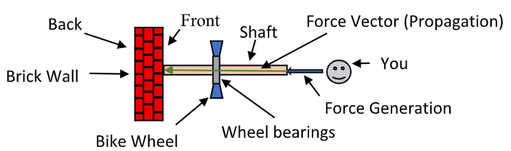
Unless the wall bends, breaks, or shifts location relative to the rest of the “solid” assembly, your force vector (showing strength and direction) ends at the front of the wall. It will not propagate any further. It has propagated from you, down the shaft lengthwise, and on to the wall. No further. You can even use the back side of the wall for other purposes. Your force vector ended at the front side of the wall.
Mechanics of Wheel Bearings and Operating Planes
The reason the vertically spinning wheel is (virtually – explanation later) unaffected is because of the physics of the wheel bearing design and the direction of the force applied. So, let’s talk wheel bearings.
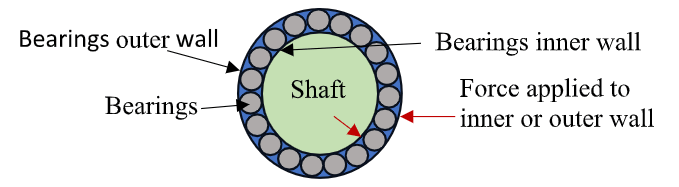
The inner wall of the bearing assembly is “permanently” attached to the shaft running thru the middle. The outer wall of the bearing assembly is “permanently” attached to the wheel. The bearings are not “permanently” attached to either of the walls. They move within the bearing channel created by the inner and outer walls. Unless the outer or inner wall bend, break, or shift location relative to the solid structures they are attached to, the bearings just roll around within the bearing channel. Separately, the inner and outer walls of the bearing assembly become the brick wall for any forces applied to either. Like you with the bike shaft against the brick wall. The applied force vectors end there.
When the force vector hits the wall, it does not make a 90-degree turn and continue propagating along the wall. This is the essence of the “operational plane” that the force is operating within. The force vector stays in its’ operating plane unless another physical force is introduced. For our bicycle example, there is a horizontal and a vertical plane. The shaft is horizontal. The wheel bearings and wheel are vertical. A 90-degree difference in their operating planes.
The design of the wheel bearing assembly does provide a direct physical contact path between the shaft and the wheel across the bearings, along the radius line when the bearings line up. But a force vector cannot propagate along that physical contact line unless something, walls or bearings, bends, breaks, or shifts location relative to each other. The outer wall ends any force vector pointing in. The inner wall ends any force vector pointing out. If nothing moves in the direction of the force vector, the vector ends there.
Environmental Factors: Solid vs. Electromagnetic Mediums
This covers the direction and operational plane parameters of the force propagation. There is one other parameter that has an impact on the force propagation. The operating environment. Solid, liquid, gas, plasma, etc. Force and energy operate according to the characteristics of the medium of its’ environment. All different environments have their own characteristics. Example: it is easier to move around in the air than it is in water. Different operational environments and characteristics.
In the E T Generator there are two operating environments. The electromagnetic environment and the solid environment. The three factors impacting force propagation are Direction, Plane of operation, and the operating environment.
Active vs. Resistive Forces
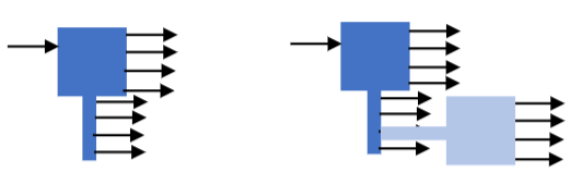
There are also two “forms” of force involved. Not using actual physics terminology, these forms can be defined as “active” and “resistive”. An active force will move whatever it is pushing against, or end at that point. A resistive force doesn’t move anything. It only resists movement in a specific direction. This is friction. The active force must be stronger than the resistive force to move the object in that direction. Even without an active force applied, the resistive force cannot move the object. It is resistance only. Since there is no movement, the resistive force does not propagate past the object (medium) that contains it. If there is a physical contact with another object, the resistive force propagates to second object, but only as a resistive force in the same direction. Remember, this is a resistive force, not an active one.
Without the physical load path, the unidirectional (one way) resistive force does not propagate in the solid operating environment. This is different in the electromagnetic environment.
Electromagnetic Field (E-Field) Dynamics
The electromagnetic environment (e-field from now on) is a product of the magnets. A magnetic field is always there around a magnet. In the architecture that the magnets are placed in around the shaft, the combination of each of the fields from each magnet creates the e-field. The solid vertical shaft sets the operating plane for the e-field as horizontal (when it spins). If the rotor is not turning the e-field between the rotor and the stator manifest as a bi-directional resistive force against the magnets to prevent them from moving (spinning) in either direction.
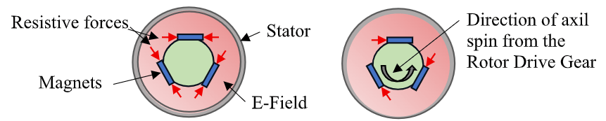
If the shaft is spinning, the only resistive force that is applicable is the one in opposition to the direction of movement. The resistive force in the same direction as the spin is still there. It just isn’t doing anything. Along for the ride and waiting for a force it can oppose. In physics technical terms, there is a lot more to it than this. But these are the force vectors that are most important and impactful to the concept. It is the design that decides which direction the shaft must spin. That spin of the axle propagates the bidirectional resistance force in the e-field to a unidirectional resistance force in the solid environment.
This is the impact of propagating the resistive force from the electromagnetic environment to the solid environment. Now we have a specific direction, plane of operation, and operating environment. The only consideration now is the level of active force needed to overcome the resistive force to spin the rotor shaft. This comes from the Rotor Drive Gear assembly. NOT the Tug Train.
Force Propagation and RPM Multiplication
The Rotor Drive Gear Assembly is stand alone with respect to load path availability. If it is not touching, there is no force propagation. All in the solid environment, it starts in a specific direction in a specific plane of operation. It finishes in that specific direction and plane creating one force load path from start to finish. Conceptually, it is just a basic RPM multiplier configuration. A small gear, on a short shaft, with a large gear. All three are part of one solid part. Put the small gear on a drive gear, and the big gear spins at the same RPM. Cascade these parts and you get RPM multiplication.
The load path for the drive force applied to the start first gear of the Rotor Drive Gear Assembly is determined by the solid environment characteristics. First, the definitional difference between two types of active force vectors in the solid environment:
- Force: pressure in a specific direction (straight)
- Torque Force: pressure in an angular direction (curved)
Resistive force is not active. It can’t move anything. The force direction is straight at the point of contact, but opposing the active force, regardless of the type of active force.
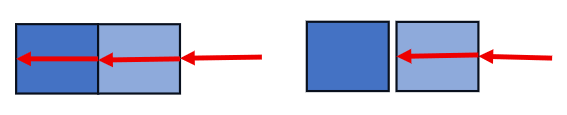
For any given solid, active force is propagated depending on the molecular lattice structure of the solid medium. Push on one end of a shaft, the force propagates straight. A solid will propagate any active force from the point of contact to the entire solid structure.
If a second solid structure is in contact with the first solid, the input force is felt over the entire combined solid. Unless solid #1 bends, breaks, or relocates, the force applied to solid #2 from the tab on #1 will be equal to the input force. Straight force propagation in a solid. That can be converted from straight to torque with a specific hardware configuration. The force actually remains straight, but the load path trajectory curves so the force is always pushing in that trajectory.
Angular Deflection and Parabolic Load Paths
The load path within a spinning solid depends on the point of contact for the input force. From that point the force will propagate to the entire solid along a radius line of the spinning solid.
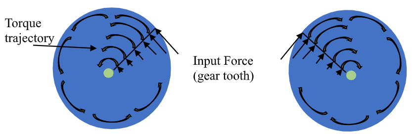
Due to the architecture and anchor in the center the input straight force is converted to torque and propagates around the center pivot point. Angular force vector. Very little, if any, of the torque is “redirected” to point in to the center. When a straight force is applied to one tooth of a gear, the entire solid gear propagates that force around the center. If you position a second gear up against it, the same force trajectory will be created. Just in the opposite direction of rotation. The final load path for the Rotor Drive Gear Assembly is determined by these force trajectories.
This series of parabolic arcs load path is a result of the placement of the anchor shafts for these gears. All of the gears in the Rotor drive train are anchored to the solid structure of the Rotor Platform. They are just tabs as part of the one solid structure. Any forces applied to the anchor shafts are being propagated to the entire Rotor Platform Structure.
This load path, considering all force propagation factors, is only possible if the shafts holding the wheel bearings for the drive gears are all anchored on the same solid. Also, they must be specifically oriented in the opposite direction relative to any resistance force applied.
If the shaft holding these gears is oriented in the same direction the resistive force is pointing, that resistive force is directed straight down the shaft. This has no impact on the direction the shaft is travelling as part of the Rotor Platform solid structure rotating at one revolution per day. Any 90-degree leakage that does get propagated thru the bearings is applied to the totality of the Rotor Platform solid structure.
The Rotor Drive Gear Assembly is a vertical operating environment. The interface at each end is to a horizontal gear. The first gear interfaces at 90 degrees to the Stator Platform. This requires that the last gear must interface to a horizontal gear also. The entire Rotor shaft is spinning in a horizontal plane. The Rotor shaft design must include the function of transferring the load path from that horizontal plane to the vertical load path. That is achieved with the Rotor assembly drive gear.
Isolation of the Tug Train from Structural Loads
That, finally, brings us back to the Tug Train. The Rotor Platform is supported by the Drive Gears between the Rotor and Stator Platforms. There is no support from the Tug Train. The Rotor Platform and the Tug Train never touch each other directly. Because of the design of the bearing assemblies the drive gears are spinning around, none of the weight load of the Rotor Platform has a load path to the Tug Train. That is due to the characteristics of the solid gear, not the bearing assembly itself. The weight load does not crush the bearing assembly.
All of this means that the loads to overcome by the Tug Train consist of:
- The weight of the Drive Gear Assembly (sliding, not lifting).
- The resistance felt by the Tug Train that is created when the shaft for the bearings to the drive gears is pushed forward by the rotational travel of the Drive Gear Assembly due to the Tug Train. This considers force propagation in a solid and bearing assembly design.
Active force from the axle (Tug Train) propagates straight along the entire load path through the bearing assembly inner wall, through the inline bearings, through the outer wall of the bearing assembly to the solid gear. When the gear is spinning, the load force vector remains stationary and does not spin with the gear. The travel of the Tug Train, and the rotation of the earth, creates the torque (angular) force to spin the drive gear. Note that the Rotor Plate (free spin) direction of travel is the exact same as the torque force of the gear, and the forward force from the Tug Train, at the point of solid contact between the gear and plate.
Since the earth is not going to stop, all forces are lined up for the forward travel of the Drive Gear Assembly that the Tug Train is pushing sideways. In essence, the rotor Platform is being pushed by the Drive Gears and the Tug Train. But the Tug Train would only feel resistance if the train were travelling faster than the earth is turning. Then the Tug would have to overcome some of the earths torque. And that ain’t gonna to happen. This is the only solid contact point path between the Rotor Platform and the Tug Train. As for that contact path being a load path, that 90-degree thing is raising its’ ugly head again. There is resistance load on the Tug Train from the Drive Gear Assembly due to forward motion. But it is limited.
Conclusion: Feasibility and Planetary Considerations
With those limited load responsibilities, the functionality of the Tug Train should be conceivable. The train doesn’t fight the electromagnetic resistive forces. It doesn’t support the Rotor Platform weight. The load resistance on the train is limited by design. From just a look at the facts (no, I didn’t do all the physics math), it appears that the energy needed to power the Tug Train does not come close to the amount of energy that may be generated by the E T G, using the full torque force of the rotating earth as the input. Therefore, the Earth Torque Generator can provide enough output to both power the Tug Train and provide a substantial watts per hour output for public use.
One final note. I intentionally limited my idea to the chain of physics. That doesn’t mean I didn’t look at the “issues and concerns”. The “practicality, application, etc.” that I removed from consideration may point at not building this idea. For instance, harvesting energy from the torque of the earth does remove energy from the rotation. Slowing the rotation of the earth could be real. Estimated to be measured by millimeters per decade. But these things are considered only if someone is trying to engineer this. I only wanted to put the valid chain of physics on the table. I have already gotten what I wanted. To trigger thought and new ideas.
This concludes my conceptual description of the Earth Torque Generator. I present this as proof of concept. The rotation of the earth in, electricity out.


Need Help? Please Leave a Comment! We value your input—Kindly keep it relevant to the above topic!