Sometimes we make electronic circuit designs, and then we see that one single TRIAC cannot take all the big current of a very heavy load. This heavy load can be a huge heater, a big motor, or too many lights. In this condition, we get a simple idea. We think that we can connect two TRIACs together in parallel. We do this to divide the current load, so then we can double the total current capacity.
But if you connect two TRIACs directly in parallel without putting extra parts to match them, then the circuit will burn immediately. This article will show you the big problems of using parallel TRIACs. And let us check the correct way to connect the wires, since we want to show you the exact mathematics to make it work safely without any danger.
The Main Problem: Current Hogging
Every small semiconductor part has little differences from the factory. If you buy two TRIACs with the same name and from the same packet, then also they have small differences in their gate sensitivity and their internal forward voltage drop (V_F).
When the trigger signal comes to start them, then one TRIAC will always turn on a little bit faster than the other TRIAC. The exact time when this fast TRIAC turns on, then the voltage on both parallel parts falls down very quickly to the conduction voltage level. This level is only about 1V to 1.5V. Because this voltage drops so fast, then the second slow TRIAC does not get enough voltage to turn on.
So now, the first TRIAC has to carry 100 percent of the total heavy load current all alone. It gets very hot quickly, fails because of thermal runaway, and then it makes a short circuit. Since the first part burns out, then all the heavy current goes forcefully into the second TRIAC. This makes the second TRIAC also burn immediately.
The Solution: Ballast Resistors on the MT2 Side
To fix this bad problem, then you must put current-sharing ballast resistors (R1 and R2) inside the circuit. You must put these resistors carefully on the Main Terminal 2 (MT2) side of the TRIACs. And you must put the heavy load also on the MT2 high side.
Putting these resistors on the Main Terminal 1 (MT1) side is a big mistake that many people make. Since the gate trigger voltage works by taking reference from MT1, then any changing voltage drop on a resistor at MT1 will shake the gate reference voltage. This will cause bad switching or the TRIAC will not turn on. But if we keep the resistors on the MT2 side, then the MT1 pins stay joined tightly to the AC Neutral line. So then this gives a very steady gate-to-MT1 voltage reference. Now let us look at the diagram to see how everything connects.
Circuit Connection Description
Now let us trace the path of the wires from the main power plug to the small control pins:
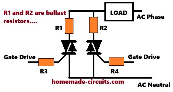
- High Side Power Path: The AC Live (Phase) wire goes straight into the first point of the Load. The second point of the Load becomes a common junction point. This common point divides into two ways. One way goes to one side of Ballast Resistor R1, and the other way goes to one side of Ballast Resistor R2. Now, the other free side of R1 connects to the MT2 terminal of TRIAC 1. And the other free side of R2 connects to the MT2 terminal of TRIAC 2.
- Low Side Return Path: When we look at the MT1 terminal of TRIAC 1 and the MT1 terminal of TRIAC 2, then we must join them together with a thick wire or a fat copper line on the board. This joined point goes straight to the AC Neutral wire.
- Gate Control Path: You must never join the gate pins directly to each other. The main trigger wire coming from your optocoupler or driving circuit must divide into two separate paths. It must go through two different gate resistors (R3 and R4). One resistor connects to the Gate pin of TRIAC 1, and the second resistor connects to the Gate pin of TRIAC 2.
How to Calculate the Ballast Resistor Value
We find the smallest value for the ballast resistors by looking at the biggest voltage difference between the two TRIACs and the biggest current difference we can allow.
The simple school formula is: Minimum Resistance = Maximum Voltage Mismatch / Allowed Current Imbalance
Let us do a simple calculation example. We have a total load of 20A RMS and we want to use two parallel TRIACs.
Step 1: Find the target branch current. If the current divides perfectly, then each TRIAC takes exactly half of the total load: Target Current = 20A / 2 = 10A
Step 2: Choose the allowed current imbalance. To keep the TRIACs safe, then the current difference must be very small. For example, we allow only 1.5A difference between the two paths. So now we let Allowed Current Imbalance = 1.5A.
Step 3: Find the maximum voltage mismatch. Standard TRIAC datasheets show a forward voltage drop of nearly 1.4V. A safe and standard guess for factory difference between two same parts is 0.2V. So we have Maximum Voltage Mismatch = 0.2V.
Step 4: Calculate the minimum resistance with our values: Minimum Resistance = 0.2V / 1.5A = 0.133 Ohms We round this up to a standard market value, so we get 0.15 Ohms.
Calculating Resistor Power Rating
Since all the branch current flows through these ballast resistors all the time, then they will produce a lot of heat. You must calculate the power rating with this formula: Power = (Branch Current * Branch Current) * Resistance
Let us use our numbers: Power = 10A * 10A * 0.15 Ohms = 100 * 0.15 = 15 Watts
For safety and long life, then you must always double this watt value so the parts do not get too hot or burn. So then you must choose ceramic wirewound resistors or aluminum cover resistors rated for at least 25 Watts or 30 Watts.
Practical Design Tips
Component Derating: We must never use the circuit at its full double capacity. If you use two 16A TRIACs, then do not use it for a 32A load. Keep the total maximum load near 25A to 28A because of small current errors.
Thermal Management: You must fix both TRIACs on a big and good metal heatsink. Use mica tape or silicone pads if the metal back of your TRIACs is not isolated. Since keeping their temperature same stops more current mismatch, then this is very important because semiconductor nature changes with heat.
Snubber Circuit: If you are running an inductive load like a heavy transformer or a motor, then you must add an RC snubber network across the MT1 and MT2 lines. This is usually a 39 Ohm resistor and a 0.01 microfarad capacitor in series. We do this to stop high voltage sparks from turning the TRIAC on by mistake.


Need Help? Please Leave a Comment! We value your input—Kindly keep it relevant to the above topic!