In this post I will show how to construct a circuit which can measure the speed of any vehicle on roads and highways. The proposed circuit is kept stationary at a place where the vehicles are suspected to over-speed. If any vehicle goes beyond the speed limit, the circuit alerts immediately. We will be looking the code, circuit diagram and logic how the speed of the vehicle is measured.
Objective
Over speeding causes 75% road accidents according to accidental death report 2015 in India, that’s a huge number. Most traffic police tries to detain the motorists who dangerously drive their vehicle beyond city speed limit.
Not every time a traffic police can stop an over speeding vehicle and charge them. So a device called speed camera is installed where the motorists are suspected to over speed such as frequent accident prone areas, intersections etc.
We are going to build something similar to speed camera, but in a much simplified way, which can be installed inside a campus such as school, college or IT parks or just as a fun project.
The proposed project consists of 16 x 2 LCD display to showcase the speed of each vehicle passing through; two laser beams which are placed apart exactly 10 meters to measure the speed of the vehicle while interrupting those laser beams.
A buzzer will beep when a vehicle is passed; indicating that a vehicle is detected and the speed of each vehicle will be displayed on the LCD display. When a vehicle is going beyond the speed limit the buzzer will beep continuously and speed of vehicle will be shown on the display.
NOTE: Speed of the vehicle will be displayed on LCD regardless of the vehicle is going over speed or under speed.
Now let’s see the logic behind the circuit for measuring speed.
We all know a simple formula called speed – distance – time formula.
Speed = Distance / Time.
• Speed in meter per second,
• Distance in meter,
• Time in seconds.
To know the speed, we have to know the distance say “x” traveled by a vehicle and time taken to cover that distance “x”.
To do this we are setting up two laser beams and two LDRs with 10 meter distance in the following fashion:
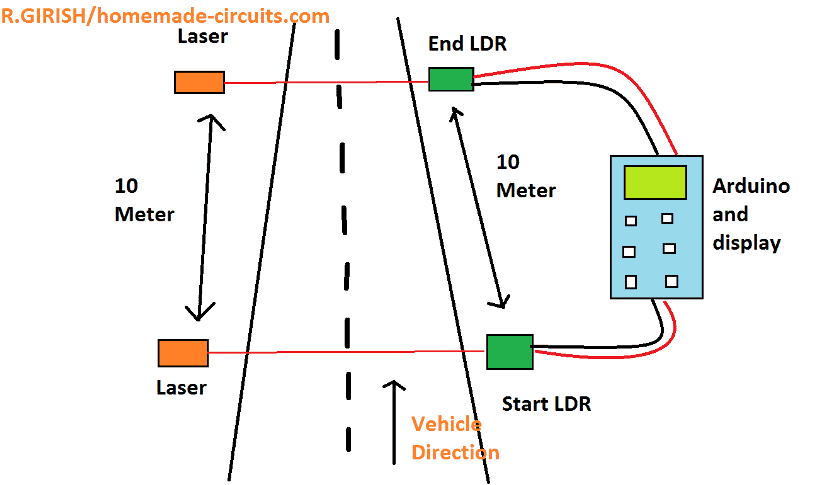
We know the distance is 10 meter which is fixed, now we have to know the time in the equation.
The time will be calculated by Arduino, when the vehicle interrupts the “start laser”, the timer begins and when the vehicle interrupts the “end laser” the timer stops and applying the values to the equation Arduino will find the speed of the vehicle.
Please note that speed of the vehicle will only be detected in one direction i.e. start laser to stop laser, to detect the vehicle in another direction another same setup has to be place on opposite direction. So, this is ideal for places like school, collage etc. where they have IN and OUT gates.
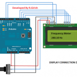
Now let’s see the schematic diagram:
Connection between Arduino and display:
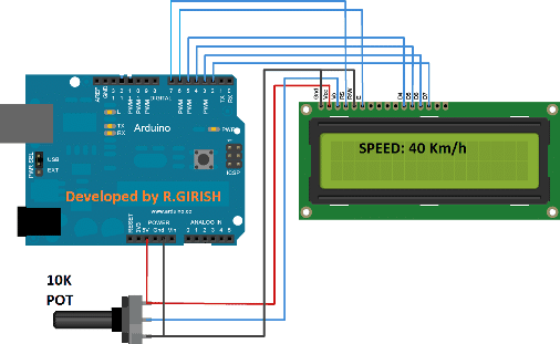
There above circuit is self-explanatory and just connect the wiring as per the circuit. Adjust the 10K potentiometer for adjusting the display contrast.
Additional Wiring Details:
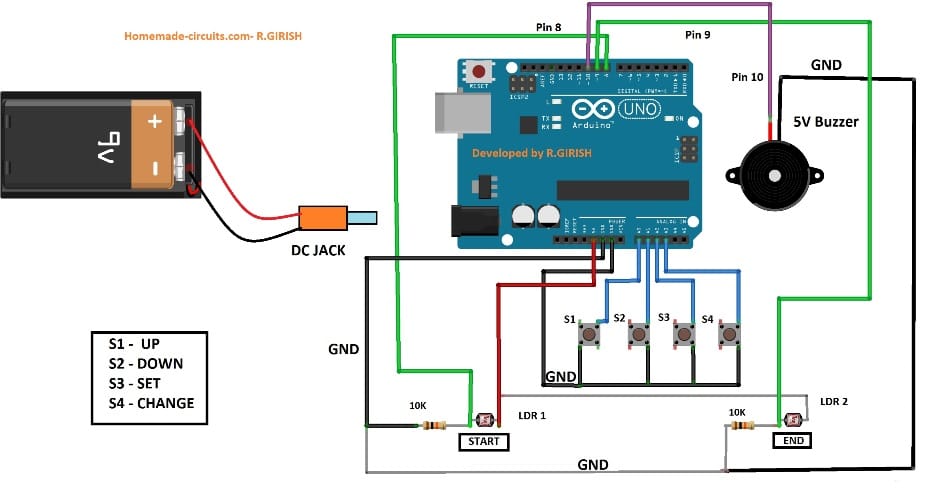
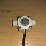
The above circuit consists of Arduino, 4 push buttons, two 10K pull down resistors (don’t change the value of resistors), two LDRs and one buzzer. The function of 4 push buttons will be explained shortly. Now let’s see how to mount the LDR properly.
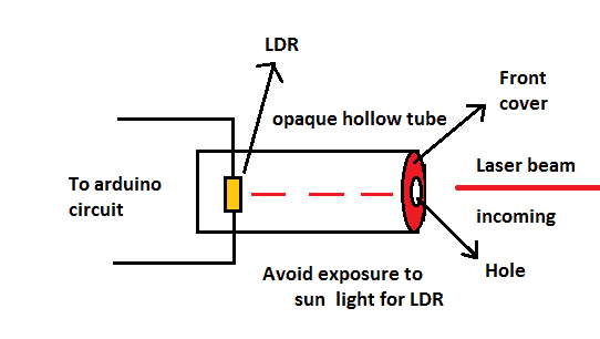
The LDR must me covered from the sunlight properly, only the laser beam should strike the LDR. Make sure that your laser module is powerful enough to work in a bright sun shine.
You can use a PVC pipe for the above purpose and paint it black inside the tube; don’t forget to cover the front part, use your creativity to accomplish this.
Program Code:
#include <LiquidCrystal.h>
#include <EEPROM.h>

const int rs = 7;
const int en = 6;
const int d4 = 5;
const int d5 = 4;
const int d6 = 3;
const int d7 = 2;

LiquidCrystal lcd(rs, en, d4, d5, d6, d7);

const int up = A0;
const int down = A1;
const int setBtn = A2;
const int changeBtn = A3;
const int startLaser = 8;
const int endLaser = 9;
const int buzzer = 10;

const float km_h = 3.6;
int distance = 10;

int speedLimit = 0;
unsigned long timerStart = 0;
float elapsedTime = 0;
float speed = 0;

bool speedSet = false;
bool laserAligned = false;
bool alertShown = false;

void setup()
{
  pinMode(up, INPUT_PULLUP);
  pinMode(down, INPUT_PULLUP);
  pinMode(setBtn, INPUT_PULLUP);
  pinMode(changeBtn, INPUT_PULLUP);
  pinMode(startLaser, INPUT);
  pinMode(endLaser, INPUT);
  pinMode(buzzer, OUTPUT);

  digitalWrite(buzzer, LOW);

  lcd.begin(16, 2);
  lcd.clear();
  lcd.setCursor(0, 0);
  lcd.print(F("vehicle speed"));
  lcd.setCursor(0, 1);
  lcd.print(F("detector"));
  delay(1500);

  if (EEPROM.read(0) != 100)
  {
    setSpeedLimit();
    EEPROM.write(0, 100);
  }

  testLaserAlignment();
}

void loop()
{
  if (digitalRead(changeBtn) == LOW)
  {
    setSpeedLimit();
  }

  if (digitalRead(startLaser) == LOW)
  {
    timerStart = millis();
    while (digitalRead(endLaser) == HIGH)
    {
      delay(1);
    }
    elapsedTime = (millis() - timerStart) / 1000.0;
  }

  speed = (distance / elapsedTime) * km_h;

  lcd.setCursor(0, 0);
  lcd.print(F("speed:"));
  lcd.print(speed, 2);
  lcd.print(F(" km/h "));

  lcd.setCursor(0, 1);
  if (speed > EEPROM.read(1))
  {
    lcd.print(F("overspeed alert"));
    if (!alertShown)
    {
      alertShown = true;
      for (int i = 0; i < 45; i++)
      {
        digitalWrite(buzzer, HIGH);
        delay(50);
        digitalWrite(buzzer, LOW);
        delay(50);
      }
    }
  }
  else
  {
    lcd.print(F("                "));
    alertShown = false;
  }
}

void setSpeedLimit()
{
  int speedValue = EEPROM.read(1);
  lcd.clear();
  lcd.setCursor(0, 0);
  lcd.print(F("set speed limit"));
  lcd.setCursor(0, 1);
  lcd.print(F("km/h:"));
  lcd.setCursor(6, 1);
  lcd.print(speedValue);

  while (true)
  {
    if (digitalRead(up) == LOW)
    {
      speedValue++;
      lcd.setCursor(6, 1);
      lcd.print(speedValue);
      delay(200);
    }

    if (digitalRead(down) == LOW)
    {
      speedValue--;
      lcd.setCursor(6, 1);
      lcd.print(speedValue);
      delay(200);
    }

    if (digitalRead(setBtn) == LOW)
    {
      EEPROM.write(1, speedValue);
      lcd.clear();
      lcd.setCursor(0, 0);
      lcd.print(F("limit set to"));
      lcd.setCursor(0, 1);
      lcd.print(speedValue);
      lcd.print(F(" km/h"));
      delay(2000);
      break;
    }
  }
}

void testLaserAlignment()
{
  lcd.clear();
  lcd.setCursor(0, 0);
  lcd.print(F("testing laser"));
  lcd.setCursor(0, 1);
  lcd.print(F("alignment..."));
  delay(1500);

  while (true)
  {
    if (digitalRead(startLaser) == HIGH && digitalRead(endLaser) == HIGH)
    {
      lcd.clear();
      lcd.setCursor(0, 0);
      lcd.print(F("laser alignment"));
      lcd.setCursor(0, 1);
      lcd.print(F("status: ok"));
      delay(1500);
      break;
    }
    else if (digitalRead(startLaser) == LOW && digitalRead(endLaser) == LOW)
    {
      lcd.clear();
      lcd.setCursor(0, 0);
      lcd.print(F("both lasers not"));
      lcd.setCursor(0, 1);
      lcd.print(F("aligned"));
      delay(1000);
    }
    else if (digitalRead(startLaser) == LOW)
    {
      lcd.clear();
      lcd.setCursor(0, 0);
      lcd.print(F("start laser not"));
      lcd.setCursor(0, 1);
      lcd.print(F("aligned"));
      delay(1000);
    }
    else if (digitalRead(endLaser) == LOW)
    {
      lcd.clear();
      lcd.setCursor(0, 0);
      lcd.print(F("end laser not"));
      lcd.setCursor(0, 1);
      lcd.print(F("aligned"));
      delay(1000);
    }
  }
}
Code Explanation
Now let us explain this improved code step by step.
First we include the necessary libraries, liquid crystal and eeprom because we need an LCD and persistent storage.
We define pins for LCDRs and d4 d5 d6 d7
We define pins for up, down, set button, change button, start laser, end laser, and buzzer.
We define constants like km_h = 3.6 to convert m/s to km/h and distance = 10 meters.
We declare variables: speed limit, timer start, elapsed time, speed, speed set, laser aligned, alert show.
In the setup function, we set pin modes: input_pullup for up-down set and change buttons.
We set startLaser and endLaser pins to input.
We set the buzzer to output and turned it off.
Then the LCD begins, shows vehicle speed detector text for 1.5 seconds.
Now we check that if eeprom address 0 ! = 100, then it means first run or reset, so we call the setSpeedLimit() function and write 100 to eeprom address 0.
After that, we call testLaserAlignment().
The function shows testing laser alignment and checks start and end lasers until both are aligned, then shows status OK.
In the loop function, we check if the change button is pressed, then we call setSpeedLimit() again to allow the user to change the speed limit.
When the start laser button is pressed, we start the timer by millis(), then wait until the end laser is pressed, then we calculate to elapse in seconds.
We calculate speed = (distance / elapsed time) * km_h
We print speed on LCD.
Then, if speed > stored the speed limit in eeprom address 1, 1 we show an overspeed alert and sounded a buzzer 45 times.
We clear the alert and stop the buzzer.
In the setSpeedLimit function, we show an interface to increase or decrease the speed limit using up/down buttons.
When the set button is pressed, we store a new speed limit to eeprom and show confirmation.
In the testLaserAlignment function, we keep checking laser alignment status if both are aligned, we break, and we continuously show a specific alignment error message every second.
This code simple, non-blocking for normal operation.
It works reliably, is easy to customize the speed limit and shows clear status.
Circuit Operation
Now let’s see how to operate this circuit:
• Complete you circuit and upload the code.
• The distance between two lasers / LDRs should be exactly 10 meter, no less or no more, Otherwise speed will be miscalculated (shown in the first diagram).
• The distance between the laser and LDR can of your choice and circumstances.
• The circuit will check for laser misalignment with LDR, if any please correct it as per the information displayed on the LCD.
• Initially the circuit will ask you to enter a speed limit value in km/h beyond which the circuit alerts, by pressing up (S1) and down (S2) you can change the number on the display and press set (S3), this value will be saved.
• To change this speed limit, press button S4 and you can set a new speed limit.
• Now take a motor bike drive at 30 km/h and interrupt the laser beams, the circuit should show you a number very close to 30 km/h.
• You are done and your circuit is ready to serve your campus safety.
Author’s prototype:
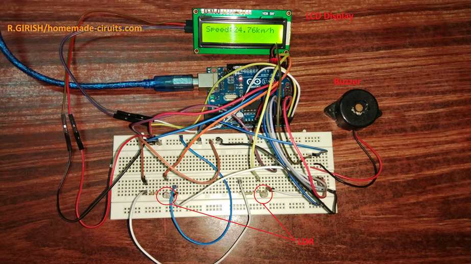
If have any questions regarding this traffic police vehicle speed detector circuit, please feel free to ask in comment section, you may get a quick reply.


Comments
Hi.
Interesting stuff.
I am interested in building something that would measure car speed , camera to identify speed limit
Highlight in red if outside speed limit.
Hi, currently I don’t seem to have such a circuit design, if I happen to comes across this circuit I will surely let you know..
May not work in countries which do not follow lane discipline , Like india !!