The presented universal power supply circuit can be used just for anything, you can use it as a solar battery charger, bench power supply, mains battery charger circuit, or for any desired application regardless of the voltage and current range, which are extremely flexible and fully adjustable.
Main Features:
The mains features of this power supply is that it is highly flexible, and will allow you to get a variable voltage from 0 to 30 V, and a variable current from 0 to 3 amp. Both the parameters can e controlled through a potentiometer.
The current limit can be upgraded by suitably increasing the rating of VT1, and by adjusting the value of R20.
Using a Single LM324 as the Main Control Device
The design of a simple opamp based power supply is not complex and utilizes ordinary parts such as IC LM324, a few BJTs and other associated passive components, yet it is too flexible and can be calibrated to any desired voltage and current range, right from 0 to 100V, or 0 to 100 amps.
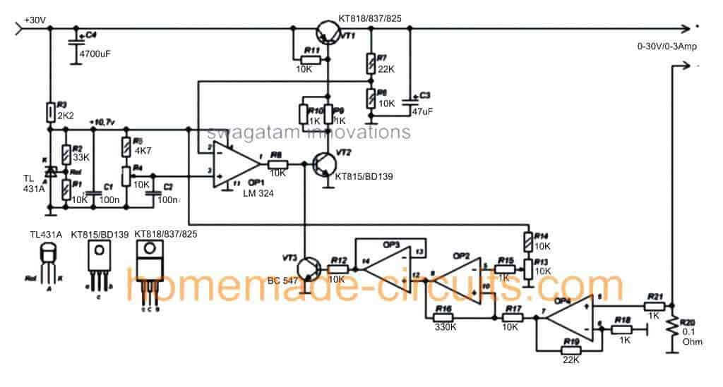
I accidentally found this design from an online website and found it quite interesting, although I already have a similar design published in this site by the name zero drop solar charger circuit, the above shown circuit looks more meticulously designed and therefore is more accurate.
Referring to the above proposed universal power supply circuit diagram, the functional details can be understood with the help of the flowing points:
How the Circuit Functions
The IC LM324 forms the heart of the circuit and becomes responsible for all the involved complex processing.
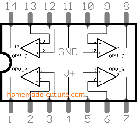
It's a quad opamp IC meaning it has four opamps in one package, and all the 4 opamps (OP1----OP4) from this IC can be seen effectively employed for their respective functionalities.
The input supply which is derived either from a mains transformer or from a solar panel is suitably stepped down using a shunt zener network VD1 to provide a safe operating voltage for the IC LM324 and also for generating a stabilized reference for OP1 non-inverting input, via R5 and preset R4.
OP1 is basically configured as a comparator, wherein its pin3 is applied with a set reference, and its pin2 is connected with a potential divider across the output of the power supply for detecting the final voltage across the load.
Depending upon the setting of the R4 which can be a pot, the OP1 compares the level of the output voltage delivered by VT1 and trims it down to the specified level. Thus, the pot R4 becomes responsible for determining the effective output voltage and can be adjusted continuously for getting the desired voltage across the indicated output terminals of the circuit.
The above operation takes care of the variable voltage feature of the proposed universal power supply circuit. VT1 and VT2 must be appropriately selected as per the input voltage range for enabling the devices to perform correctly without getting damaged.
The variable current feature of the design is implemented through the remaining three opamps, that is collectively by the opamps OP2, OP3, and OP4.
OP4 is configured as a voltage sensor and amplifier, and it monitors the voltage developed across R20.
The sensed signal is fed to the input of OP2 which compares the level with a reference level set by the pot (or preset) R13.
Depending on the setting of R13, OP2 toggles OP3 continuously such that the output from OP3 switches off the driver stage VT1/VT2 whenever the output current tends to go above the fixed level (set by R13).
Therefore R13 here can be effectively used for setting up the maximum allowable current across the output for the connected load.
The resistor R20 may be appropriately dimensioned for calibrating the maximum allowable current for the load, which can be tweaked by R13 from 0 to maximum.
The above versatile features makes this universal power supply circuit extremely efficient, accurate and fail proof so that it can be used for most electronic application one can think of.
The design can be expected to be fully short circuit and overload protected, provided VT1 and VT2 are appropriately cooled by mounting them over adequate heatsinks.



Questions & Answers
sincer esti o comoara de om.mereu ne uimesti cu postarile tale.esti un om deosebit.
gogotu, can you please translate the language in English??
Is this design itself an inverter? What Kind and does require a transformer?
It's an AC to DC variable power supply circuit, the DC needs to be supplied from a suitably rated transformer
Is this design itself an inverter? What KVA? does require a transformer?
hi swagatam, i am using a android tablet for to visit your website, but i not succeed to see good the diagram. can you tell me as i can do? thank you so much.
regards erchiu
hi franco, in my android mobile all the diagrams are distinctly clear….not sure what might be causing it in your tablet.
Hello Swagatam,
Thank you for this post. I intend to build a lead acid battery charger for a 12V 1.3Ah battery, using a solar panel (planning to use a 12V 5W one). I am relatively new to electronics and hence seek your help to understand and bring up the required circuit.
Can I use the circuit in this post for this purpose? I intend to keep the battery always connected to this charger circuit and drive a few LEDS as load by the battery. The intention being that the battery is continuously charged during day time.
If this circuit can be used for the charger – are there any concerns if the input voltage drops low and cannot charge the battery (for e.g. at night, when the output from the solar panel will drop significantly); should I add any additional control circuit to detect low input voltage and detach the charger from the battery? Also in such conditions when VT1 is not conducting(?) when the battery is fully charged, will the battery discharge through R6 and R7?
Thank you!
Hello NPI, the above design is too elaborate for your application, so it may not be appropriate.
You can use the first circuit that's shown in the following article:
sorry here's the link:
https://www.homemade-circuits.com/2013/03/simple-dc-ups-circuit-for-modemrouter.html
just replace the adapter input with your solar panel input.
Thank you, Swagatam.
I will check this out. What should be the value of R1 (after the TIP122) to use for my battery (for a 1.3Ah, I guess the charging current should be around 100-130mA)?
it is not too critical actually, you can use any resistor which allows around 100mA to 200mA current to the battery…you can confirm it with some trial and error.
ok swagatam,
thank you.
i follow your blog!
regards erchiu
Sir swagatam,l'm previleged to be regualar follower to have been taping ur ideas and knowledge from you blog.i think you will find time to clearify me on the these issues,in home made circuit they were two circuits about alternator power booster,one from you another one hobbyist.the one from you, can i use same type of capacitors the guy used for your circuit?or did he used polarise capacitor for his circuit?thirdly can your own circuit carry electric pressing iron or boiler with small generator of 650va etc Thanks for your reply
ndukwe, you will need to use only non-polar capacitors for the design specified by me, and those must be rated at above 400V minimum….the value of the capacitors will determine how much load it can sustain with the boosted voltage. electrolytic capacitor will blow of immediately, so never use electrolytic polarized ones.
yes it will be able to handle iron and boiler provided the capacitors are of high value….you can use fan capacitors for the application.
Sir good day to you
Please suggest me How to choose mov voltage Does have any formula?
How to select Max continuous voltage or Max clamping voltage ?
Rajkumar, MOVs are determined by their clamping voltage spec, suppose if you select a 400V MOV then it can be expected to activate and protect whenever the voltage spikes occur at around 400V….
…only the clamping voltage is normally considered for MOVs…
I see a problem here. Under high current R20 will cause a voltage drop on load. This is no good, current sensing better to be done before regulator so this drop is compensated.
R20 is specifically for sensing and restricting high current above a certain range as selected by the user…R20 can be modified anytime for increasing the current output, as desired
no matter where R20 is introduced it will still drop the voltage across the load…
Hi Swagatam,
I have been really looking for something like this since long. Thanks for the post.
I have a few questions.
1) I already have a transformer with 50 volts DC output capable of 40 amps max.
Can I use this transformer as input (50 vdc) for this circuit? What changes should I make to VD1 so that I can use 50 vdc as input?
2) How do I calculate the value of R20 to make it suitable for the max 40 amps the transformer is capable of? Also what should the wattage be of R20?
3) What changes do I need to make to VT1, VT2, VT3 to make this circuit capable of 40 amps?
Please do suggest any other changes which you may feel fit for making this circuit.
Thanks for all your help.
Vimal
Hi Vimal, thanks
1) with a 50v transformer, the rectified output could be well over 56V
no issue though, ….you can use TIP36C for the power transistor VT1, for VT2 you can use MJE340, and VT3 can be a BC547
R20 can be calculated as follows:
R2 = V/40 where V is the reference voltage at the (-) pin of OP4
…sorry TIP36 is rated at just 25 amps.
instead you can try 2N5684 for VT1
Hi Swagatam!
Thanks for the quick reply.
Are all the resistors in the circuit regular 1/4 watt resistors?
In the schematic,resistors R1, R2, R5, R6, R7, R10 have symbols with 2 cross lines on them. Does this mean anything? I tried searching the internet, but couldn't find any info on this.
Also R3 has a single straight line in the resistor symbol?
If different wattages are required for any of the resistors in the circuit, could you please specify? (Considering max voltage to be 50 volts DC and max amps 40 amps).
My Trafo output is 50 volts DC rectified. Would the VD1 stage in the schematic work fine as it is?
Thanks for your patience, and please bear with my questions as I am still a novice at electronics.
Appreciate your time.
Hi Vimal, you can calculate the wattage by using Ohm's law as shown below:
I = V/R
and followed by this
P = I^2 x R
so at 50V for example the R3 2k2 wattage would be
I = 50/2200 = 0.022amps
therefore P = (0.022)^2 x 2200 = 1.06 watts or 1.5 watt (safer value)
except R3 all can be 1/4 watt rated according to me….I am too not sure about those lines, may be those were specified in the actual article…however you can use 1/4 watt 1% MFR resistor for extreme safety and should be more than enough
use 1% MFR 1/4 watt resistors for all except R3, and R20
if VT1 transistor is rated at over 60V then there would be no problems
respected Sir, what are the changes required to make it 0-30v 0-5a variable power supply, also could you please elobrate a bit about digital panel meters etc. thanks
Gowhar, you can simply use an LM338 based circuit for your requirement.
please specify what exactly you would want to know regarding panel meters…I'll try to help.
Hi Swagatam !
Referring to my previous questions on this circuit, I checked the data sheet of VD1 (TL431A). The max cathode (Vka) voltage for TL431A is 37 volts dc.
My trafo is rated for 50 volts dc after rectification.
Should I change VD1 to any other type? or would this work fine as it is?
Please suggest if I need to make any changes to the complete VD1 network to make it compatible to 50Vdc of my trafo.
For calculating the wattage of R20, is there someway to calculate the reference voltage at (-) pin of OP4?
Just going by the simple calculation of max output of 50 volts and 40 amps, the resistance value comes out to be (R= V/I)= 1.25 ohms.
Using the power calculation formula P= I^2 x R = 1600 * 1.25 = 2000 watts.
This seems a little impractical at first sight.
I guess I am doing something wrong in this calculation and as you have mentioned, I have to take the reference voltage at (-) pin of OP4 so I guess the reference voltage might not be the full output 50 volts. Can you help on this please?
Thanks for your help!
Hi VM,
VD1 can be simply replaced with a 1 watt zener diode with a voltage rating of anywhere between 3 and 6V.
your calculation regarding R20 might not be correct because here it's referenced with the opamp input and not directly with the load.
the easiest way to identify the right value would be to connect an LED in series with the emitter of the VT3, when this begins illuminating you can be sure that the current control function is working for that particular resistor value… and then go on changing this resistor value until you find the one which illuminates the LED at around 40 amps.
but make sure to connect a 4.7V zener diode in series with the VT2 emitter to compensate the LED drop.
Hi Swagatam,
Regarding your last response for using a 1 watt zener diode 3 – 6 volts instead of VD1 (TL431), in the circuit for using input voltage of 50 to 60 volt dc from the trafo, could you please clear the following doubt?
a) TL431 has 3 terminals (K, A, Ref), one of which is used for reference.
b) A zener diode will have only 2 terminals. How and where should I connect this?
Should I simply replace TL431 with the zener and not use the reference point? or is there any other way in which I should connect?
Thanks for your help bro.
Hi VM,
yes, simply replace TL431 with the zener and do not use the reference point
you can remove R1, R2, now they won't be needed, and connect the zener exactly where the anode/cathode of the TL are shown connected.
SIR what is TL41A in the circuit ?
KT815 , KT816 can these be replaced by any power transistors such as TIP32C, 2N5904 etc . ? if the replacement is possible what about the current output ?
TL431 is an IC and a form of enhanced zener diode
the transistors can be replaced with other types having higher V, I specs.
Current can be increased by suitably changing R20 value.
how can i change the voltage and current in this circuit ? which potentiometers allow these ?
i have explained it in the article
sir why some resistors like R6 R7 in this diagram is represented by two curved lines drawn inside them ?
Does it state that those are high watt ones ?
those are supposed to be 1% MFR types but it is not strictly required
I am designing an universal 0 to 30 V bench power supply with a 300 W transformer. Sir please say whether the following things are possible
(1). There would be separate output terminals other than the variable voltage ( 0 to 30 V ) such as fixed 12 V , 9 V and two 5 Vs but with current control features
(2). The above circuit is implemented to get the variable current and voltage feature.. but can i get maximum of 25 A with this configuration ?
(3). An LM317 in place of 7812 in the circuit given in the following link and output voltage adjusted to fixed 12V . Can it be used as a separate 12V source as said in Question (1) ?
3.bp.blogspot.com/-XgFFR9YXaLg/UbqwRRnhn7I/AAAAAAAAEV4/VpQhXEXk8Rg/s1600/tip36+high+current+circuit.png
(4). If the case that said above is possibe is it ok in taking direct output from that fixed 12V source to 7809 and 7805 to get 9V and 5V sources ?
For reference i am sending one picture of my design to your email ( hitman2008 ).. plz check it out
RT, yes all those features can be easily implemented, but the current selection will need to be done through a rotary switch which can configured to select different calculated resistor values for the 1 ohm/5 watt resistor as shown in the linked circuit
Sir can a TIP36C replace a 2N3055 ?
WHAT WILL BE THE MAXIMUM CURRENT THAT CAN BE TAKEN FROM TIP36c ?
RT, TIP36 is PNP and 2N3055 is NPN, you can try 2N2955 instead
TIP36 can provide 25 amps….2N2955 only upto 15 amps
Hello Sir. What modifications should I make if I have a 30V transformer 3A, and want a 0-24V 0-2A output? Thank you so much.
Hi Swagatam,
You make my day with this project, thank you.
Few questions, please:
1. Did you build/test this circuit?
2. If yes, could you measure the ripple voltage when the power source is fully loaded?
3. What values should be expected for this ripple voltage?
Thank you again,
Dan.
Thanks Dan! No I haven't tested it yet, but I have studied the design thoroughly and it looks OK to me.
Hi Swagatam,
After long I finally got the time to make this power supply. I tried to draw the schematic in NI Multisim, when I try to simulate it, it does not work. Also the voltage does not change at the output.
I have incorporated all the changes suggested by you in my previous posts.
I also noticed that in NI mulstisim, there are lot of variants of LM324. I dont know which to use. For my schematic, I used LM324AD.
I can email you the schematic file or upload it somewhere, would it be possible for you to check what is going wrong? I really need this power supply pretty bad.
Hope you can help me on this.
Thanks.
Hi VM, Making the circuit on simulator will not help, it won't allow you to assess the design correctly, because a simulator results can be misleading and confusing…it's better to make it practically on a breadboard or veroboard and then tweak the results as per the required specs.
I have always trusted my brain simulation more than simulators and has always paid off
Ola Swagatam,
sou apenas um aprendiz de eletronica e o seu topico me chamou muito a atenção, porem surgiu uma duvida:no começo da descrição voce diz que pode ir de 0 a 100v e 0 a 100A, quais mudanças devo fazer para atingir tal proporção.
Se puder me ajudar ficarei muito agradecido.