In this post I have explained an LED controller circuit having a boost and dimming facility specifically designed for underwater shooting application. The idea was requested by Mr. Svein.
The Circuit Request
I came across your blog at https://www.homemade-circuits.com and thought I'd ask you a question regarding building or modifying a LED driver.
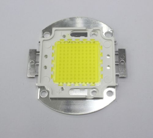
I planning to build a LED underwater light with a 100w LED SMD.
For the LED module I'm planning on using one of the following types:
For the driver I'm looking at one of the following:
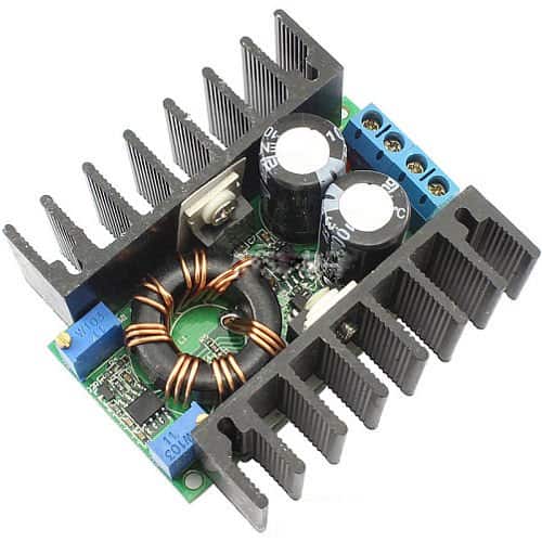
or
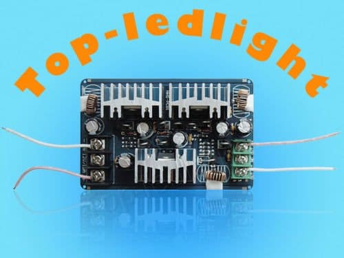
or
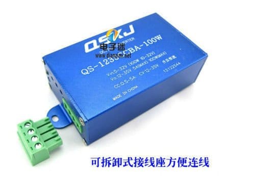
I need the driver to boost/step up voltage from 11-13v to the required voltage of the LED module, and in this case that would be 30-36V and of course be able to current limit the output.
But what I also want, that none of the drivers listed above provides is being able to dim, or set maybe 3 to 5 different intensities like 10%, 30%, 50%, 70% and 100%.
I would also like the driver and on/off-function to could be controlled by a reed/magnet switch to avoid running a switch through the watertight casing. Keeping the size down is also beneficial.
Is there any way you would think it is possible to modify the drivers listed? Or is it possible to build something like this by myself?
If you do have the time to consider a circuit like this it could be very helpful.
I am planning to have two separate light heads with one 100W LED SMD in each, and run them from the same battery. It is for video lights, so one light on each side of the camera.
If the control of these two lights could be controlled by the same switch it would be nice also 🙂
Great site btw, thank you for sharing all your information!
Kind regards,
Svein

The Design
The proposed LED underwater light booster circuit with dimming feature could be build using a few 555 ICs as presented in the following description and the above circuit diagram:
The design is basically a controlled PWM generator circuit using a couple of versatile 555 ICs.
The one on the left is rigged as an astable for producing a high frequency square wave which is fed to the complementary IC2 555 stage wired in its standard PWM generator form.
IC2 responds to the fed pulses at its pin2 and compares it with the potential at its pin5 as set by the attached 10k preset.
The potential at pin5 set by the 10k preset voltage divider determines and varies the output PWM content at pin3 of IC2 by proportionately varying the duty cycle of the PWMs.
Lower potentials at pin5 of IC2 results in higher space ratio thereby forcing the LEDs to go dimmer and vice versa.
The above PWMs finally is applied to the gate of an N-channel mosfet which transforms the data into an amplified, boosted voltage across the LEDs with the help of the inductor L1.
The mosfet along with L1 forms a simple boost circuit which converts the 12V supply to the required 36V directly across L1 for the LEDs to get illuminated optimally.
The BC547 at pin5 of IC2 is positioned as a current sensor and controller, its base resistor Rx decides the maximum safe current allowable for the LEDs, and may be calculated as per the following formula:
Rx = 0.6/I where I is maximum current limit as per the LED specs.
How to Wind L1
It could be a matter of some experimentation. Begin by winding arbitrarily a few turns of 22 SWG magnet wire over a ferrite rod of any dimension. Connect it with the circuit and measure the boosted voltage across the coil (without connecting the LEDs).
Now simply divide the measured voltage with the number of turns used, the result would give you the turns per volt of the coil assembly. Next, its just a matter of optimizing the number of turns for acquiring the required magnitude of volts, which is around 33V in the proposed under water LED light booster, dimmer circuit.


Comments
Ok, thank you.
I made a part list from this project that i will share here:
R1=180k
r2=100
R3=470
R4=2k2
R5=100
R6=1k
R7=10
RX=
P1=10k
C1=1n
c2=10n
c3=1uF
C4=10n
BC547
BC557
D1= 2V7
D2=1N4148
BUZ10
IC1 = 555
IC2 = 555
that looks fine! just make P1 = 1k preset for a better response.
Hi Claudia,
The result for the formula I = 0.6/R will be in Amps…..not in mA
sir please help me. I want to make a mobile power bank with charging facility. Sir I have seen all your circuit diagram of dc mobile charger.In all circuit we input 6v to 12v battery.These batteries contain high weight and better for use in home or where these batteries are available but in journey like train,bus etc we cannot bring this method.we need a small and low weight devices.So please sir show me a circuit diagram for it.input power can be 1.5v to 3.7v.sir please take serius and reply soon.I am searching this circuit from 3-4 months.
utkarsh, you can try the following suggestion:
https://www.homemade-circuits.com/2012/11/homemade-cell-phone-emergency-charger.html