The ultrasonic hand sanitizer circuit detects the presence of human hand through reflected ultrasonic waves, and triggers a relay solenoid pump momentarily for dispensing the sanitizing liquid on the hands of the user.
The project uses the popular HC-SR04 ultrasonic sensor module for the required sensing function.
Using HC-SR04
The HC-SR04 ultrasonic sensor module is built usng a couple of specialized ultrasonic transducers rated to work and respond at a frequency of around 40 kHz.
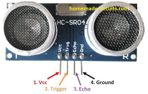
The module has 4 pinouts for configuring into the intended driver circuit.
The supply pinouts are indicated with Vcc and Gnd pins. Where Vcc is the positive 5V input for the module, and the Gnd is supposed to be connected with the negative line of the input power supply.
The trigger pin works with a 10 us pulse which activates the two transducers for transmitting and receiving the reflected ultrasonic wave.
When a series of reflected signals is detected, the "Echo" pin becomes high for initiating the external relay or the solenoid or any preferred load.
Interfacing HC-SR04 with Arduino
In order to process the HC-SR04 module, and enable it to work as a precision ultrasonic proximity detector, we need a microcontroller unit such as an Arduino for the task.
When appropriately programmed with the code as given below, the Arduino becomes compatible with the HC-SR04, for the intended hand proximity detection and activation of sanitizer dispensing mechanism.
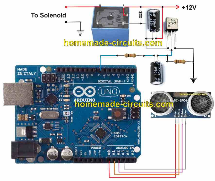
The interfacing wiring diagram of the Arduino with HC-SR04 and the relay stage can be seen in the following diagram:
Operational Details
The operational procedure of this ultrasonic hand sanitizer circuit is simple, and can be understood with the following points:
The Arduino provides the 10 us activation pulse to the HC-SR04 modules trigger pulse, which enables the module to send and receive the reflected pulse train from the target, which is the hand of the user.
This reflected data is sent to the rduino from the Echo pin of the HC-SR04 module.
The Arduino process the signal and enables stable DC output at pin7 of the board, which is connected with the relay driver stage via a 10k resistor and a 100uF capacitor.
The pin#7 of Arduino is supposed to stay high as long as the HC-SR04 modules continues to detect the users hand within the set proximity.
This mean the re;ay will also stay switched ON during this period, which we don't want.
To make sure that the relay and the attachwd dispensing mechnaism or pump is actated only for a few seconds, a capacitor is placed in series with the base of the BC547.
When pin#7 becomes high due to the presence of a human hand, the BC547 conducts only for so long as its base 100uF is fully charged, which happens within a couple of seconds.
Once the 100uF is fully charged, the BC547 base is inhibited from the base drive, and it stops conducting, switching OFF the relay and disabling the attached hand sanitizer dispensing mechanism.
When the hand is removed, the HC-SR04 stops sending the Echo signal to the Arduino, which flips its pin#7 to logic zero.
At this point, the 100uF base capacitor starts getting discharged via the Arduino pin#7 and the right side 10k ground resistor.
Program Code
The entire program code for the above discussed ultrasonic hand sanitizer circuit using HC-SR04 and Arduino is given below:
const int trigger = A1;
const int echo = A2;
int vcc = A0;
int gnd = A3;
int OP = 7;
long Time;
float distanceCM;
float distance = 15;  // set threshold distance in cm
float resultCM;
void setup()
{
pinMode(OP,OUTPUT);
pinMode(trigger,OUTPUT);
pinMode(echo,INPUT);
pinMode(vcc,OUTPUT);
pinMode(gnd,OUTPUT);
}
void loop()
{
digitalWrite(vcc,HIGH);
digitalWrite(gnd,LOW);
digitalWrite(trigger,LOW);
delay(1);
digitalWrite(trigger,HIGH);
delayMicroseconds(10);
digitalWrite(trigger,LOW);
Time=pulseIn(echo,HIGH);
distanceCM=Time*0.034;
resultCM=distanceCM/2;
if(resultCM<=distance)
{
digitalWrite(OP,HIGH);
delay(4000);
}
if(resultCM>=distance)
{
digitalWrite(OP,LOW);
}
delay(10);
}
Warning: The proposed ultrasonic hand sanitizer circuit has not been tested practically by the author. The idea was inspired from this article, and modified appropriately for enabling the required momentary ON/OFF function for the dispenser pump, or the solenoid.

Comments
I tried this, can anyone guide me circuit diagram connect ultrasonic sensor,relay,
microcontroller.
Dear Swagatam,
Greetings of the day.
Is it possible to design circuit which shall switch on the power supply say SMPS or Voltage Stabiliser only when the load say R.O Filter ( to be switching on depending upon its water level if full or lesser) or Fridge cycle swicthes on ( depending upon the T ). My purpose is if this kind of circuit design is possible then it shall conserve or save substantial power otherwise the SMPS/Stabiliser always remains in On position immaterial whether load is on or not.
Hello Belbrook, yes that seems possible, I’ll try to design it and post it. But you should have asked this question under an SMPS or power supply artcile, your question is not related to hand sanitizer topic.