In this post I have explained a simple circuit design which ensures a perfectly stabilized 220 V or 120 V mains voltage across the connected load, without using relays or transformers, rather by the use of accurately dimensioned and self adjusting PWM pulses. The idea was requested by Mr. Mathew.
Warning: Circuits I have explained below are not isolated from mains AC, and therefore are very dangerous to touch in the powered and open condition. You should be extremely careful while building and testing these circuits, and make sure to take the necessary safety precautions. The author cannot be held responsible for any mishap due to any negligence by the user
Technical Specifications
About power optimizer (stabilizer) I need a simple circuit board which can be installed in our power guard ( capacitor bank) with SPD and ELCB for 1ph and 3ph.
At present we are producing it without any electronics circuit in it. So we are planning to add one circuit board for power optimizer to balance the voltage drop or over voltage.
Our product is in a good demand, So we are planning to introduce our power guard with a voltage stabilizer for our 1ph and 3ph unit. In this case we need a very simple less cost circuit board for our new models.
I hope you understand what I need exactly. As I told you in my earlier mail that if you can design the PCB or supply PCB with components will be an advantage because in our country components is very difficult to find. Our 1ph is 220v/50Hz with 12k and 3ph /415v/50Hz 40k
I look forward your reply soon.
Kindly add me in Skype for any discussion or in viber , whatsup Thanks Mathew
The Design
As requested, the mains voltage stabilizer needs to be compact and preferably a transformerless type. Therefore a PWM based circuit looked to be the most appropriate option for the proposed application.
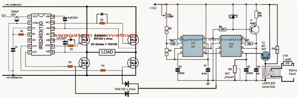
Here the mains AC input is first rectified to DC, then converted to a square wave AC, which is finally adjusted to the correct RMS level for obtaining the required stabilized mains output. So basically the output will be a square wave but controlled at the correct RMS level.
The Rt/Ct of the IRS2453 IC should be appropriately selected in order to obtain a 50 Hz frequency across the H-bridge network.
The shown PWM mains stabilizer circuit basically consists of two isolated stages. The left hand side circuit is configured around a specialized full wave H-bridge inverter IC, and the associated power mosfets.
To learn more about this simple yet highly sophisticated H-bridge inverter, you may refer to this article named: "Simplest full bridge inverter circuit"
As may be seen the diagram, here the intended load is placed across the left/right arms of the full bridge mosfet.
The right hand side circuit which is made by using a couple of 555 IC stages forms the PWM generator stage, wherein the generated PWM is mains voltage dependent.
Here the IC1 is configured to generate square wave signals at a particular set consistent rate, and feeds the IC2 for transforming these square waves into corresponding triangle waves.
The triangle waves are then compared with the potential at pin#5 of IC2 in order to generate a proportionately matching PWM signal at its pin#3.
That implies, the potential at pin#5 can be adjusted and tweaked for getting any desired PWM rate.
This feature is exploited here by attaching an LDR/LED assembly along with an emitter follower across the pin#5 of IC2.
Inside the LED/LDR assembly, the LED is tied up with the mains input voltage such that its intensity proportionately varies in response to the varying voltage of the mains.
The above action in turn creates a proportionately increasing or decreasing resistance values over the attached LDR.
The LDR resistance influences the base potential of the emitter follower NPN, which accordingly tweaks the pin#5 potential, but in an inverse ratio, meaning as the mains potential tends to increase, the potential at pin#5 of IC 2 is proportionately pulled downwards and vice versa.
As this happens the PWM at pin#3 of the IC is narrowed as the mains potential increases and widened as the mains decreases.
This automatic adjustment of the PWMs is fed at the gates of the low side mosfets of the H-bridge which in turn makes sure that the voltage (RMS) to the load is appropriately adjusted with reference to the mains fluctuations.
Thus, the mains voltage becomes perfectly stabilized and is maintained at a reasonably correct level without using any relays, or transformers.
Note: The rectified DC bus voltage is obtained by appropriately rectifying and filtering the AC mains voltage, so here the voltage could be well around 330V DC


Comments
the circuit is very useful. it can be made more practical if it included the calculations for Rt & Ct. Thank u
hai swagatam ,
i need to convert dc 700 volt to ac and reduce it to low voltage for battery charging ,because i have panels connected series for agri 5 hp solor pumpset which is run by solor vfd ,so i dont want to disturb the connection and i want to keep changeover switch inbetween dc bus voltage from panels and use it to home by ups when not in agri use
the circuit that you have referred is a simple low power inverter circuit, and it's a step-up inverter, it cannot be used for stepping down a voltage.
for stepping down a voltage you'll need a buck converter as suggested by me in the earlier comment or you can also use a buck flyback converter for the same.
Google "buck flyback converter circuit", you will find many good examples.
Hi shiva,
you can try the simple buck converter circuit shown in this article:
https://www.homemade-circuits.com/2014/06/solar-panel-buck-converter-circuit-with.html
just make sure tat the transistors, capacitors and the mosfet are all rated at above 700V