• Skip to main content
  • Skip to primary sidebar

Homemade Circuit Projects

Need circuit help? Post them in the comments! I've answered over 50,000!

Blog | Categories | About | Contact | Calculators-online
You are here: Home / Datasheets and Components / TIP127 Datasheet [100V, 5 Amp PNP Darlington Transistor]

DIY Circuits | Learn Basics | Arduino Coding

TIP127 Datasheet [100V, 5 Amp PNP Darlington Transistor]

Last Updated on February 27, 2023 by Swagatam 4 Comments

The TIP127 is a PNP Darlington transistor commonly used for high-power switching applications. Here is the complete datasheet for this transistor:

Electrical Characteristics:

  • Collector-Emitter Voltage (VCEO): 100V
  • Collector-Base Voltage (VCBO): 100V
  • Emitter-Base Voltage (VEBO): 5V
  • Collector Current (IC): 5A (continuous), 8A (peak)
  • Base Current (IB): 50mA (continuous), 100mA (peak)
  • Power Dissipation (PD): 2W
  • Minimum hFE or DC Current gain: 1000

Thermal Characteristics:

  • Junction Temperature (Tj): -65°C to 150°C
  • Thermal Resistance - Junction to Case (RθJC): 3.125°C/W
  • Thermal Resistance - Junction to Ambient (RθJA): 62.5°C/W

Pin Configuration:

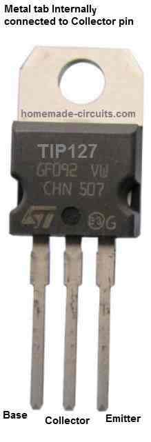
As shown in the above figure, the TIP127 transistor has three pins: the collector (C), the base (B), and the emitter (E). The pinout configuration is as follows:

  • Pin 1: Base (B)
  • Pin 2: Collector (C)
  • Pin 3: Emitter (E)

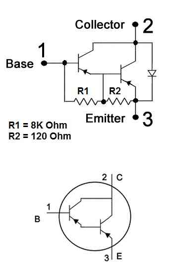
Internal Darlington Configuration

The TIP127 is a PNP Darlington transistor which has two PNP transistors configured with each other, as shown in the following diagram:

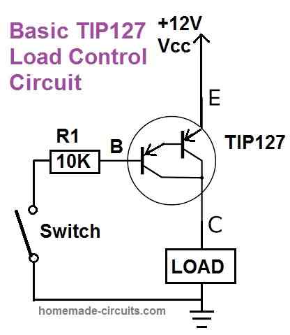
How to Switch ON TIP127 Transistor

Since the TIP127 is a PNP transistor, it can be switched ON by applying a negative potential to it base pin, as shown in the following circuit diagram:

Package Information:

The TIP127 transistor is available in the TO-220 package, which is a through-hole package with a single mounting hole. The package dimensions are as follows:

  • TO-220 Package: 10.67mm x 15.87mm x 4.83mm

Typical Applications:

The TIP127 transistor is commonly used in high-power switching applications, such as:

  • Power supplies
  • Motor control
  • Lamp dimming
  • Solenoid control
  • Audio amplifiers
  • High-current drivers

Limitations:

  • Maximum Collector Current: 5A (continuous)
  • Maximum Power Dissipation: 2W
  • Maximum Voltage: 100V

Other Features:

  • Darlington Configuration
  • High DC Current Gain (hFE)
  • Low Saturation Voltage (VCEsat)

Note: This information is taken from the TIP127 datasheet published by ON Semiconductor. Actual values may vary based on specific manufacturer and production batch.

You'll also like:

  • 110V boost converter using IRF640IRF640 Datasheet [200V, 18 Amp N-Channel MOSFET]
  • 4040 pinout diagramIC 4040 Datasheet, Pinout, Application
  • 188transistordatasheetBEL188 Transistor – Specification and Datasheet
  • PIR internal layoutPIR Sensor Datasheet, Pinout Specifications, Working

Filed Under: Datasheets and Components Tagged With: 100V, Darlington, Datasheet, PNP, TIP127, Transistor

About Swagatam

I am an electronics engineer and doing practical hands-on work from more than 15 years now. Building real circuits, testing them and also making PCB layouts by myself. I really love doing all these things like inventing something new, designing electronics and also helping other people like hobby guys who want to make their own cool circuits at home.

And that is the main reason why I started this website homemade-circuits.com, to share different types of circuit ideas..

If you are having any kind of doubt or question related to circuits then just write down your question in the comment box below, I am like always checking, so I guarantee I will reply you for sure!

Previous Post: « IC 4027 Datasheet, Pinout Working, Application
Next Post: IRF510 Datasheet [100V, 5.6 Amp, N-Channel MOSFET] »

Reader Interactions

Comments

MOSES says:
October 12, 2025 at 12:59 pm

how do we make its output voltage adjustable. this topic is rarely discussed in electronics. Many concentration is on NPN TRANSISTORS

Reply
Swagatam says:
October 12, 2025 at 5:28 pm

Do you mean with an emitter follower configuration? You just have to do the opposite of what you do in an NPN based emitter follower…

Reply
MOSES says:
October 12, 2025 at 5:36 pm

yes. ok I get it now. meaning the positive voltage has to enter through the emitter this time and then the output is through the collector as the pot is adjusted .

Reply
Swagatam says:
October 13, 2025 at 8:14 am

Yes, the load and the positive supply must be in series with the emitter, and the base should be connected to a potential divider which provides a variable voltage across the base/ground of the PNP transistor. The collector can be directly connected to the ground.

Reply

Need Help? Please Leave a Comment! We value your input—Kindly keep it relevant to the above topic! Cancel reply

Your email address will not be published. Required fields are marked *

Primary Sidebar

circuit simulator image

Subscribe to get New Circuits in your Email

Categories

  • Arduino Projects (95)
  • Audio and Amplifier Projects (133)
  • Automation Projects (18)
  • Automobile Electronics (103)
  • Battery Charger Circuits (87)
  • Datasheets and Components (109)
  • Electronics Theory (149)
  • Energy from Magnets (27)
  • Games and Sports Projects (11)
  • Grid and 3-Phase (20)
  • Health related Projects (27)
  • Home Electrical Circuits (13)
  • Indicator Circuits (16)
  • Inverter Circuits (95)
  • Lamps and Lights (159)
  • Meters and Testers (71)
  • Mini Projects (28)
  • Motor Controller (68)
  • Oscillator Circuits (28)
  • Pets and Pests (15)
  • Power Supply Circuits (91)
  • Remote Control Circuits (50)
  • Renewable Energy (12)
  • Security and Alarm (64)
  • Sensors and Detectors (106)
  • SMPS and Converters (34)
  • Solar Controller Circuits (60)
  • Temperature Controllers (43)
  • Timer and Delay Relay (49)
  • Voltage Control and Protection (42)
  • Water Controller (37)
  • Wireless Circuits (31)

Other Links

  • Privacy Policy
  • Cookie Policy
  • Disclaimer
  • Copyright
  • Videos
  • Sitemap

People also Search

555 Circuits | 741 Circuits | LM324 Circuits | LM338 Circuits | 4017 Circuits | Ultrasonic Projects | SMPS Projects | Christmas Projects | MOSFETs | Radio Circuits | Laser Circuits | PIR Projects |

Social Profiles

  • Twitter
  • YouTube
  • Instagram
  • Pinterest
  • My Facebook-Page
  • Stack Exchange
  • Linkedin

Recent Comments

  • Swagatam on Simplest Full Bridge Inverter Circuit
  • Swagatam on Inverter LC Filter Calculator
  • Majaha Masuku on Simplest Full Bridge Inverter Circuit
  • Srecko Kovacevic on Inverter LC Filter Calculator
  • Swagatam on How to Make Dog Barking Preventer Circuit using High Frequency Deterrence

© 2026 · Swagatam Innovations