In this article I have explained a simple temperature controlled relay circuit which can be switched ON/OFF depending on the temperature on its temperature sensor.
Meaning, when the temperature on its temperature sensor rises above a set threshold point, the relay switches ON, and when the temperature drops below the threshold, the relay switches OFF.
Any load connected across the relay contacts thus also switches ON/OFF depending on the temperature level of the sensor.
Using a Thermistor
Clearly for this temperature switch relay circuit to work we require some sort of electronic sensor whose characteristics change with temperature.
You will find a couple of primary types of components that exhibit ideal temperature sensing qualities: semiconductor junctions and thermistors.
For this circuit we have decided to work with a thermistor.
Thermistors are exclusive varieties of resistors constructed from heavy metal oxides and built to possess highly varying "resistance versus temperature" properties.
Circuit Description
The following figure exhibits our simple temperature controlled relay switch circuit, which even with its ease-of-use has the ability of providing precise and dependable results over an extensive range of temperatures.
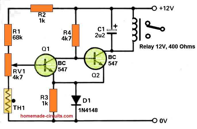
The preset, RV1 enables the working temperature to be established, and is tweaked to make sure that below the preferred cut-off point, the voltage across base of Q2 is adequate to allow it to be in the switched on condition.
As the thermistor temperature increases, the voltage around the base of Q1, which is extracted from the resistive divider network comprising of R1,R2, RV1 and TH1, starts falling, ultimately permitting Q1 to turn off.
The moment Q1 turns off the voltage around the base of Q2 goes up and the relay is switched on.
The diode, D1 delivers temperature compensation to the a pair of transistors, and C1 functions like a back EMF preventer for the relay. As indicated in the diagram, the circuit temperature range could be anywhere around 35 to 100 degrees centigrade.
As long as the relay is in an inactive condition, the current draw of the circuit is very little at around 2 to 3mA. Therefore, the circuit could be powered from either battery packs,or a tiny DC power sources.
Construction
A straightforward circuit which is explained here might be constructed over a tiny PCB. When constructed, the circuit must be two times inspected for proper positioning of diodes, transistors and capacitors, and only after that should be powered ON.
The thermistors possess no built-in polarity, and could therefore be hooked up without worrying about its direction.
How to Set Up
To set up the circuit, adjust the preset RV1 to roughly at the midway, and then slightly heat up the thermistor using some sort of external heating source, for example you can take a light bulb, or a soldering iron in close proximity to the thermistor.
Within a few seconds you should find the the relay clicking ON and any kind of device connected to the relay contacts could be seen switched on.
Next, as soon as the heat source moved away from the thermistor, the thermistor will start cooling down, until its temperature decreases below the trip-point and the relay switches OFF, turning off the connected load.
Applications
The relay output of this temperature controlled relay circuit could be attached to either an alarm device, or any kind of heating system, or cooling system.
For example the circuit could be used for switching ON a cooling fan as soon as the temperature is detected to be beyond a high threshold.
It could used for cooling heatsinks or for cooling semiconductor devices in inverters.
While picking out a appropriate location for the temperature sensor, be cautious to stay away from putting it in a situation where it will likely be exposed to external heating agents.


Questions & Answers
Please, your component designation confuse me. I do understand 68K or 22MFD or 22ufd but when you mix in another format such as a 4k7 resistor or a 2u2 capacitor, I am not sure what the value is, please explain.
Thank you so much for the vast number of circuits you have punlished JACK
Hi, thanks for the question, I will explain you what they mean.
4k7 = 4.7 kilo ohm
2u2 = 2.2 microfarad
Thank you sir. then why the two different ways of expression? What is wrong with sticking with the old traditional method such as: 1.5 ohms or 33uuF. how would they be identified this other way?
You are welcome Jack, there’s no problem with the traditional method, however, the new method allows the value to look compact in size
Thank you sir, I do understand. Have a nice weekend, OUT
You too have a great weekend Jack, all the best to you!
Hi Patrick,
I appreciate you question, but think your question is asked under a wrong article, it should have been asked under an automotive article.
Anyways I have found a related circuit from an old magazine, you can check out this diagram:
I have another design posted in the following link:
https://www.homemade-circuits.com/automobile-engine-rpm-servicing-meter-circuit-analogue-tachometer/
Hi, good morning!
I have a question.
What’s TH1 value?
Kind regards!
João Almeida
Hi,
TH1 value can be a 10K thermistor
Hello sir,
Good morning sir, I cheked your circuit diagram , wonderful and very helpful,
But sir , I need 5 volt 100 amps dc circuit diagram with transformer for led bunch lights, if you provide me circuit diagram its very helpful to me.
thanks sir,
I am waiting for your reply.
Hello Mohd.
What is the LED specifications, meaning what is voltage and current specifications of the LED and how many LEDs do you want to connect. However, getting a 100 amp transformer can be almost impossible.
Sir give out the steps followed in this project,2nd how could I test the product
Kevin,
The setting procedure is explained in the article.
hello sir Hume ek temperature control module bana tha jo timer module ke tarah Kam kare jese timer module me hota ha ek baar time set Karo start Karo or wo module siraf uthane time tak hi chalta fir band ho jata par kisi bhi temperature module me esa nahi ha uun me pahale upper limit set karna hoga fir lower limit fir wo kam karta ha par hume sirf ek temperature set karna ha or fir agar hamara module wo temperature reache kar le to bass off ho jaye dubara chalane ke liye hume fir se timer module se tarah start botton dabana hoga ye module hum cold to heat ke liya bana rahe the heater ke liya ke bass ek desired temperature reache karke wo off ho jaye
help sir please
Hello Neeraj, so you want a latching type of temperature controller circuit where the relay will switch OFF and “lock”, and remain locked until power is switched OFF.
You can upgrade the above circuit in the following manner:
can we add a puch to start botton in this circuit diagram and instead of relay can we use MOSFETs ?
sorry push button will not be possible. Yes mosfet is possible…
OK I will try to design that type of circuit tomorrow
sir please puch bottom ko add karna nahi to koi sa bhi botton chalega start karne ke liya
please!
You can try the following circuit:
Sorry, I don’t think this will work. This will turn ON and latch the mosfet when the temperature reaches the limit. Please let me know what type of load do you want to connect on the mosfet?
ek 12v 5amp ka heater
OK, I will try to design it soon.
thank you sir par thoda jaldi karna or aapna UPI bhi mail karna kyuki Hume aapko design ke liya thank you money bhi sand Krna hoga ????
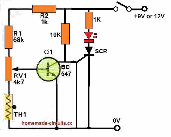
Please build and test the following setup. If you are successful then I will show you how to integrate a MOSFET with heater in this circuit, such that the MOSFET shuts off whenever the thermister is heated upto a certain high temperature.
In this circuit when you heat the thermister, at some point, depending on the setting of the RV1, the SCR will switch ON and “Latch”, illuminating the RED LED permanently.
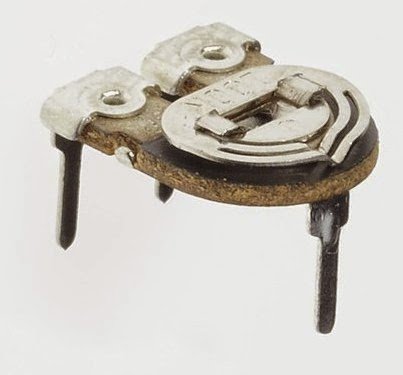
sir circuit diagram me RV1 4k7 kya hai ? (potentiometer) ??
Preset hai:
Neeraj,
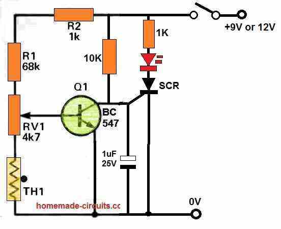
there’s a fault in the following circuit:
The line going down from SCR gate to ground must have a 1uF capacitor in the line.
Please add the capacitor.
thik hai me capacitor add kar lunga par maaf karna me aap ko pareshan kar Raha hu par iis me load kese connect kare? or SCR ki value Kiya hogi ?
Load will connect with MOSFET, which is not added yet. Please test with LED first, if it works then I will show you how to connect MOSFET with SCR.
SCR can be BT169.
https://media.digikey.com/pdf/Data%20Sheets/NXP%20PDFs/BT169_Series.pdf
or kitane voltage ka capacitor?
1uF/25V capacitor. Positive will go to SCR gate and negative will go to ground.
Power supply to circuit can be between 6V to 12V
When power is switch ON, Q1 will be ON, so SCR and LED will e OFF.
When you heat the thermister, Q1 will become OFF, and ScR will trigger ON and lock and LED will be ON
sir led on hue thermistor ko heat karne ke baad par jese hi thermistor normal temperature par aaya led off ho gayi ! Sara circuit to sahi Kam Kiya par mugha ye samajh nahi aa raha kyu ek normal temperature per aane par led off ho gayi led ko to permanently on rahana chahiye tha na jab tak me power supply na hatha du
solution sir ?
Neeraj,
Since an SCR is used it should latch up once triggered. SCR jab DC pe kaam karta hai, gate par positive trigger paate hi LOCK ho jata hai. Tumahare cirucit mein SCR latch kyon nahi ho raha hai samajh mein nahi aaraha.
How much DC voltage did you use?
Try 12V DC.
agar yeh kaam nahi kar raha to dusra circuit try karna padega…
9v wali battery use kar raha hu
9V to theek hai, kaam karna chahiye.
mene scr ke gate per 1uf 63v ka capacitor lagaya ha iis se to koi dikkat to nahi
1uF ko nikaal de dekho kya hota hai.
Aur LED ka 1K par aur ek 1K parallel mein lagao.
sir koi or solution capacitor ko hata kar bhi dekha kuch nahi huua same result koi or circuit diagram hoga ? agar nahi to Iis circuit me MOSFET or heater add kar do !
Without SCR any other circuit will be with 5 transistors with latch, OK?
If you use relay it will very easy to latch….
sir agar relay lagane ne se latch aasan ho jata hai to relay hi laga lenge relay wala circuit diagram bata do
OK, if relay circuit is OK then first make the circuit exactly as ahown in the above article. If your circuit works correctly and operates the relay, then I will show you how use the relay contacts to latch the circuit and to operate the LOAD
or sir iis circuit diagram me MOSFET or heater bhi add karna wese me heater ko 24v 10amp ke power se connect karta hu yeh module itna load sah sakat hoga ?
If you are using a relay then MOSFET will not be required.
sir mugha laga ki mene circuit hi galat joda hoga par for se naye comments ke sath circuit diagram banaya to wahi answer Mila ek high to temperature par aane ke baad led on to ho jati ha par jase hi normal temperature per thermistor aata ha led of ho jati ha scr bhi change karke dekha fir bhi!
me relay nahi lagana chahta
sir ek baar aap hi try karke dekha please ???? humra project ruk Raha ha please help Karo
sir kya hum iis me diode miss kar rahe ha kya ?
sir capacitor ko nikal ke bhi dakha kuch nahi huua sab same hi ha koi naya circuit diagram do na jo kam kare please ????
Neeraj, That means your SCR is faulty or your SCR connections are wrong, because SCR will 100% latch with DC trigger.