• Skip to main content
  • Skip to primary sidebar

Homemade Circuit Projects

Need circuit help? Post them in the comments! I've answered over 50,000!

Blog | Categories | About | Hire Me | Contact | Calculators-online
You are here: Home / Archives for Diagrams

Diagrams

10 Simple FM Transmitter Circuit Diagrams Explained

Last Updated on January 2, 2026 by Swagatam 132 Comments

two transistor FM transmitter

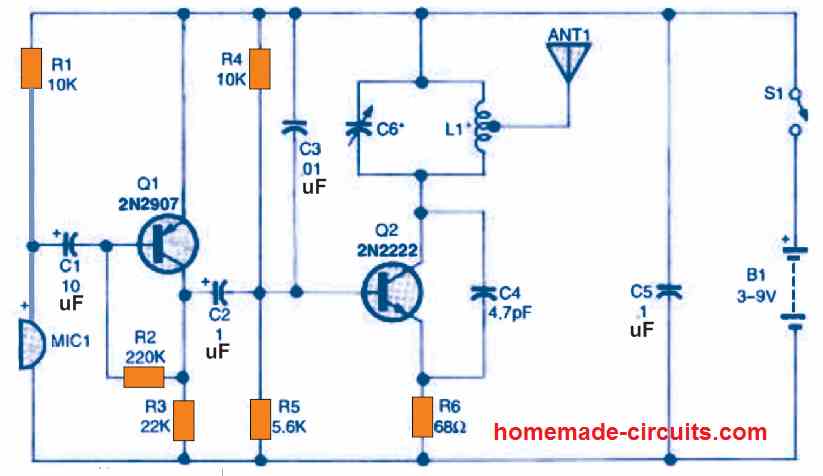
An FM transmitter circuit is a high frequency wireless device which is able to transmit voice signals into atmosphere so that it can be received by a corresponding FM receiver circuit for reproducing the voice signals in a loudspeaker. Here we’ll discuss how to build small FM transmitter circuits using 10 different methods, one that […]

Filed Under: Wireless Circuits Tagged With: Diagrams, Explained, FM, Simple, Transmitter

ACS712 Current Sensor Circuit Diagrams and Datasheet

Last Updated on July 8, 2025 by Swagatam 1 Comment

Here we are going to learn one cool and very important current sensor device which we call ACS712. This small chip that look just like a normal 8-pin IC, is actually able to sense current from any load and give us a proportional analog voltage output which we can easily feed to Arduino or any […]

Filed Under: Sensors and Detectors Tagged With: ACS712, Current, Datasheet, Diagrams, Sensor

110V, 14V, 5V SMPS Circuit – Detailed Diagrams with Illustrations

Last Updated on July 5, 2025 by Swagatam 29 Comments

smps

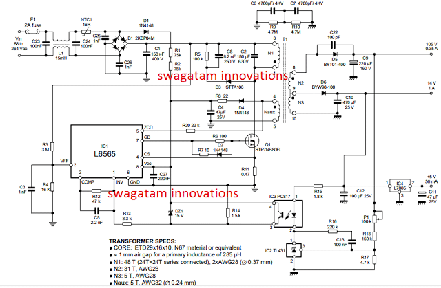
In this post I have explained how to apply the IC L6565 for making a compact multi purpose 110V, 14V, 5V SMPS circuit using minimum number of external components. Implementing quasi-resonant ZVS flyback The IC L6565 from ST Microelectronics is designed as a current-mode primary controller chip, to specifically suit quasi-resonant ZVS flyback converter applications. The […]

Filed Under: SMPS and Converters Tagged With: 110V, 14V, Detailed, Diagrams, Illustrations, SMPS

Simple Boost Converter Circuit Diagrams using Transistors

Last Updated on January 27, 2025 by Swagatam Leave a Comment

boost converter working model

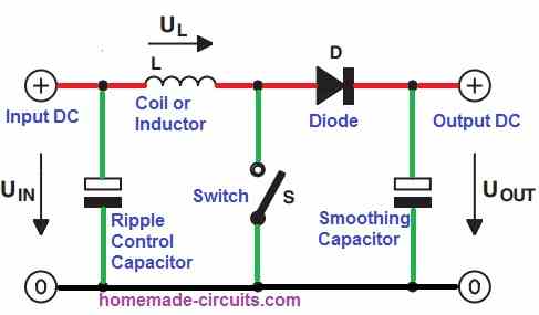
In this post I have explained a few very simple boost converter circuits using only BJTs, or transistors. Let’s learn more. What is a Boost Converter A DC boost converter circuit is designed for stepping-up or boosting a small input voltage levels to a desired higher output voltage level, hence the name “boost” converter. Since […]

Filed Under: Voltage Control and Protection Tagged With: Boost, Converter, Diagrams, Simple, Transistors

10 Simple Unijunction Transistor (UJT) Circuit Diagrams Explained

Last Updated on January 17, 2025 by Swagatam 21 Comments

UJT Pulse Generator

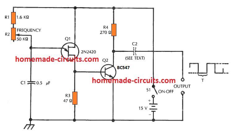
In the earlier post I have explained comprehensively about how a unijunction transistor works, in this post I will elucidate a few interesting application circuits using this amazing device called UJT. The example application circuits using UJT which are explained in the article are: 1) Square Wave Pulse Generator The first design below demonstrates a […]

Filed Under: Oscillator Circuits Tagged With: Diagrams, Explained, Simple, Transistor, UJT, Unijunction

10 Easy Op-amp Oscillator Circuit Diagrams Explained

Last Updated on January 17, 2025 by Swagatam 5 Comments

formula for calculating C1 and L1

In an op amp oscillator circuit, an op amp is configured with a resistor-capacitor feedback loop or a inductor-capacitor feedback loop, which triggers the op amp to go into an oscillating mode, generating a switching ON/OFF pulses from its output pin. The high-gain and wide passband of operational amplifier (op amp) ICs makes it possible […]

Filed Under: Oscillator Circuits Tagged With: Diagrams, Easy, Explained, Oscillator

  • « Go to Previous Page
  • Page 1
  • Page 2
  • Page 3
  • Go to Next Page »

Primary Sidebar


My Youtube Channel

Circuit Simulator

circuit simulator image


Subscribe to get New Circuits in your Email


Categories

  • Arduino Projects (95)
  • Audio and Amplifier Projects (134)
  • Automation Projects (18)
  • Automobile Electronics (103)
  • Battery Charger Circuits (88)
  • Datasheets and Components (109)
  • Electronics Theory (148)
  • Energy from Magnets (27)
  • Games and Sports Projects (11)
  • Grid and 3-Phase (20)
  • Health related Projects (27)
  • Home Electrical Circuits (13)
  • Indicator Circuits (16)
  • Inverter Circuits (100)
  • Lamps and Lights (162)
  • Meters and Testers (72)
  • Mini Projects (28)
  • Motor Controller (69)
  • Oscillator Circuits (28)
  • Pets and Pests (15)
  • Power Supply Circuits (91)
  • Remote Control Circuits (50)
  • Renewable Energy (12)
  • Security and Alarm (65)
  • Sensors and Detectors (107)
  • SMPS and Converters (45)
  • Solar Controller Circuits (60)
  • Temperature Controllers (43)
  • Timer and Delay Relay (50)
  • Voltage Control and Protection (44)
  • Water Controller (37)
  • Wireless Circuits (31)


Other Links

  • Privacy Policy
  • Cookie Policy
  • Disclaimer
  • Copyright
  • Videos
  • Sitemap

People also Search

555 Circuits | 741 Circuits | LM324 Circuits | LM338 Circuits | 4017 Circuits | Ultrasonic Projects | SMPS Projects | Christmas Projects | MOSFETs | Radio Circuits | Laser Circuits | PIR Projects |


Recent Comments

  • Swagatam on Make this Solar Powered Fence Charger Circuit
  • Swagatam on How to Make Logic Gates using Transistors
  • Swagatam on Mains High Low Voltage Protection Circuit with Delay Monitor
  • Swagatam on Pump Motor Timer Circuit Diagram with Dry Run Protection
  • Elz on How to Make Logic Gates using Transistors

Social Profiles

  • Twitter
  • YouTube
  • Instagram
  • Pinterest
  • My Facebook-Page
  • Stack Exchange
  • Linkedin

© 2026 · Swagatam Innovations