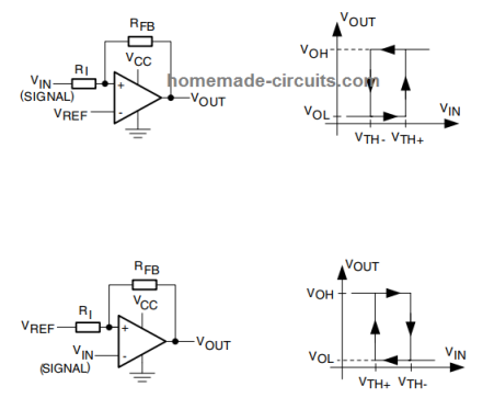
This post will help you to understand a few of the crucial comparator parameters or specifications which are generally found in comparator IC datasheets. Some of the major parameters that you may come across in the datasheet of a compartaor are: Propagation delay Current consumption Output stage type (open collector/drain or push-pull) Input offset voltage, […]
Datasheet
IC 4069 Datasheet, Pinout Working, Applications
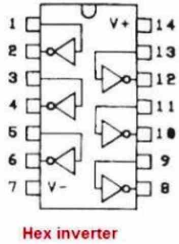
The IC 4069 is a CMOS hex inverter that contains six independent inverter gates. These are called inverters because these gates will always invert the signal at their inputs to produce an opposite signal at their outputs. Pinout diagram of the IC 4069: Understanding the Pinout Working of the IC 4069 As explained above, the […]
IC 4070 Datasheet, Pinout Working, Truth Table, Electrical Characteristics
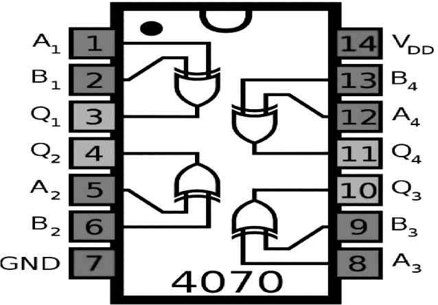
The IC 4070 is a quad 2-input XOR gate IC which is designed for a wide range of digital logic applications. The XOR function is a logical operation that produces a high output (1) only when the inputs potentials are not similar. The IC 4070 contains four independent XOR gates in a single package which […]
IC 4013 Datasheet, Pinout Details
IC 4013 is a CMOS-based dual D-type flip-flop integrated circuit. It is widely used in digital circuits for applications such as counters, shift registers, and control circuits. Below is the detailed datasheet for IC 4013. Pin Configuration: IC 4013 has a total of 14 pins. The pin configuration is as follows: Pin Name Pin # […]
IC 4016 Datasheet, Pinout Function
IC 4016 is a CMOS-based quad bilateral switch integrated circuit (IC). It may be used for a variety of purposes, including waveform generation, voltage-controlled oscillator, switching of audio and video signals, and controlling analogue and digital signals (VCO). A thorough datasheet for the IC 4016 is I have explained below: Electrical Characteristics: Pin Configuration: The […]
IC 4020 Datasheet, Pinout Functioning Explained
The IC CD4020 is a 14-bit Binary Counter IC, manufactured by Texas Instruments. It consists of 12 output pins numbered Q1 to Q14, except Q2 and Q3. Whenever an Input clock pulse is applied to the clock pin of the IC, the binary value is increased from 00 0000 0000 0000 to 11 1111 1111 […]