The proposed slow-start power supply circuit is specially designed for power amplifiers to ensure that the loudspeaker connected with the amplifier do not generate the loud and unwanted "thump" sound during power switch ON.
This also implies that the power supply will safeguard or protect the loudspeaker from the sudden inrush current transient from the power supply, and ensure long life for the loudspeakers.
With this power supply, the connected amplifier and its loudspeaker could be operated safely without the need of other form of protections, such as fuses, delay ON circuits etc.
Power Switch-ON Transient
Most of the amplifier designs, whether DIY or commercial built units, are accompanied with the downside of the generation a loud 'thump' sound on every power switch ON occasions. Normally, this is because of too rapid charging of the output filter electrolytic capacitors, which is unable to stop the initial sudden switch ON transient.
If this problem arises in a high-power amplifier circuit, there may be a high possibility of loudspeakers getting shorted anytime and burned.
An alternate idea is to upgrade the unpredictable amplifier with a slow rising voltage power supply circuit which is discussed in this article. It is fundamentally a basic transistorized regulator, enhanced with a slow-start or soft start feature.
How the Circuit Works
The complete circuit diagram of the slow soft start amplifier power supply is shown below:
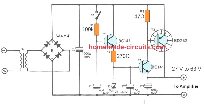
The crude supply is supplied by rectifier B and smoothing capacitor CO. Zener diode D1 offers the reference voltage, since the output voltage is lower, at around 600 mV. If it is essential, the intended voltage could be built applying a couple of series connected zeners diodes.
The overall zener voltage could be selected in between 28 V and 63 V (approximately). Switch S1 toggles the supply on and off (connected to the mains AC switch). Whenever it is closed or powered ON, the voltage across C1 goes up in around One second upto its working threshold.
The output voltage begins climbing in accordance with the rising voltage across C1 until the level where the zener diode becomes conductive or the firing threshold of the zener.
When S1 is not closed, or is open, the C1 voltage begins dropping down within approximately Five seconds, caused by the leakage through the base current feed for the transistor T1. In case the amplifier exhibits no significant switch-off voltage spikes, so that no specific turn-off procedure is necessary, it may be possible to totally eliminate the switch S1, and connect the S1 points with a wire link..
The unregulated voltage at C1 must not go beyond 80 V. It must be selected to ensure that there is sufficient voltage drop over T3 to deal with regulation specifications.
Way too high a drop would be a waste of power and even an unnecessary involvement of pricey heat sink.
The basic theory is that, with the supply input fully loaded and the inbound mains AC voltage at its minimum (anticipated) range, there should be approximately 2 volts over the series transistors on the troughs in the ripple waveform.
Alternatively, an acceptable rule of thumb, would be to allow for around 10 volts over T3 (without any load), and expect T3 will, under all circumstances require a minimal heat sink (e.g. 2 mm thick shiny aluminum, about 10 cm by 10 cm).
In severe conditions this might be furthermore essential to enhance T2 with a cooling fins or extensions.
The value of 1000 µF capacitor presented for Cv is merely indicated as a representation.
If you would be interested to precisely design the basic transformer/bridge supply also, coupled to a compatible optimum load, that could be easily calculated through the formula Q = CV (keeping in mind that the rectifier produces one hundred ripples every second.

Comments
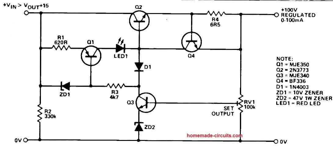
I have been trying to wire up a circuit that uses p-channel and n-channel fets [two of each] that sense instantaneous positive or negative voltage spikes. The fets turn on either a green or red led. Ideally the green led would sense the negative spike and the red led would sense the positive spike. As each led comes on, the other led would be cancelled or blocked from coming on. Plus the lit led would be delayed going off, maybe 3 seconds. I have been working with 2sk170 and 2n5462 transistors which I have at hand. I can supply the circuit that I have drawn out. Thank you for any help that you can give me.
The circuit looks OK to me except the two diodes which are placed across the 220K resistor at the gate of the bottom left p channel mosfet. These diodes must be connected between the positive line and the 220k resistor ends.
Hello, I have power amplifier equiped in an active loudspeaker, if you turn on the soft start act very fast causing thump sound in the driver.. what would be the problem. Please help me
Hi, did you build the circuit which is shown in the above article?
Hello sir,I like the idea, please sir do you have any for Inverter? I would like to have my Inverter start softly.
Evans, the soft-start facility is already included in SG3525 IC, so you can use it for the purpose
But sir,what of cd4047????
you can try connecting pin9 with ground through a 10k resistor and then add a 10uF capacitor across the positive line and pin9
Okay sir,let me try