In this post I will explain this 220V RGB slow fading LED bulb circuit step by step and we can start from the left side and slowly move toward the right side so that you can understand what each block is doing. We use many parts like 555, 4017, 33uF, D1 to D4, and others and we try to see how each one behaves with the next stage.
What Is RGB LED In This Circuit
First let us study what is meant by RGB LED here, because many people think it is one small three-pin LED however in this circuit we are not using a single RGB LED rather we are using three separate high watt LED strings.
One string emits red, one emits green, and one emits blue, meaning when these three colors are controlled in a sequence then we get the RGB effect just like a normal RGB LED.
These three basic colors can mix in different brightness levels to produce many other colors but here in this design we are not mixing them smoothly like in PWM. Instead we fade OFF one color slowly while switching ON the next color instantly.
This creates a kind of mixing color effect where the lamp goes Red then fades… then Green then fades… then Blue then fades… then Red again, giving rise to slow fading 7 color rainbow color effect on the bulb lighting.
In this circuit each color string is made by a series of 1-watt LEDs so these are three separate high-brightness LED chains.
Each chain is driven by its own TIP122 transistor and its own resistor, so the circuit basically turns ON red first, then fades it OFF, then turns ON green, then fades it OFF, then turns ON blue, then fades it OFF, and so on.
So the name RGB LED bulb here simply means the complete lamp built using red LED string, green LED string, and blue LED string, running together to show an RGB rainbow 7 color effect.
Circuit Diagram

AC To Low Voltage DC Block
We start from the left area. Here we see that C1 is 0.47uF and that capacitor is acting like a dropper so it limits the AC current without wasting power like a resistor.
We also see that R1 is 1M and that is simply discharging C1 when the circuit is removed from the mains.
When we look at R2 which is 10 Ohm 1 Watt then we find that it is protecting the diodes from switch-on surges. The D1 to D4 which are all 1N4007 make a full-wave bridge so they convert AC to DC.
Now the 1000uF/25V capacitor smoothens the DC and the zener Z1 which is 15V clamps the voltage to safe level so the 555 and 4017 can run properly.
So this whole block is giving us a stable low voltage supply from 230V or 120V AC.
555 Oscillator Block
Now we move to the 555 timer. This 555 is wired like an astable oscillator so it keeps running freely. That 500K pot and the 22K resistor decide the timing speed.
So when you increase the resistance then the pulse becomes slower and when you decrease it then it becomes faster. The output at pin 3 of the 555 provides the slow clock signal that will drive the 4017.
4017 Sequencer Block
Now we jump to the 4017 area. The clock from 555 pin 3 goes into 4017 pin 14. So the 4017 shifts one output at a time. It goes from pin 3 to pin 2 to pin 4 and so on.
Since this RGB LED bulb circuit is using only the first three outputs, so the LED colors move in a three-step sequence.
When one becomes High then the next becomes Low and when the next becomes High then the first one becomes Low.
We also see that pin 15 is connected in a way so that the IC resets automatically after these three steps and the pattern repeats again.
33uF Fade Capacitors
Now we look at the 33uF capacitors which create the smooth fading effect. Each output of the 4017 is going through a 33uF capacitor before reaching the LED group.
So when any output becomes High then the 33uF capacitor charges slowly and makes the LED group fade in gradually.
And when that output becomes Low then the capacitor discharges slowly so the LED group fades out.
Since each color group has its own 33uF capacitor, so we get a very gentle fade from one color to another.
LED Color Groups
Now on the right side we see the different LED groups. Each group is made using many LEDs in series-parallel form.
These groups are connected through diodes so that no back-feeding happens between the color channels.
So when any color group receives voltage from its 4017 output then that group glows softly and fades based on the charging and discharging of the 33uF capacitor.
Overall Working
So now we can see everything together. The AC is reduced through a capacitive dropper and then converted to DC.
The 555 produces a slow pulse. The 4017 distributes this pulse one by one to three outputs. Each output feeds a color group through a 33uF capacitor so that color fades in and fades out.
So we get a smooth color movement that goes Red to Yellow to Blue and then it comes back to Red again.
High Power RGB Bulb Circuit
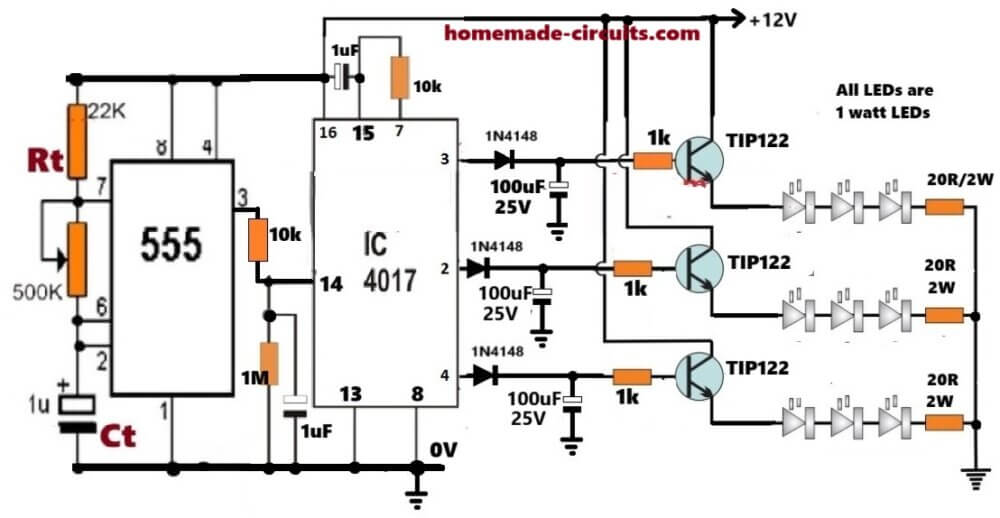
This next design is also a simple homemade red, green, blue LED light mixing effect circuit that slowly changes between red, green, and blue colors by fading one color out and fading the next color in, simulating a rainbow color effect. But i uses 1 watt LEDs, so the light power is significantly high and powerful...
Circuit Diagram
Working Of The Slow Fading RGB LED Bulb Circuit
Let us now try to understand this whole RGB fading circuit in. We first look at the left side where the 555 timer is sitting and working like a small heart that keeps beating at a fixed rate.
We set this pulsing speed by Rt and Ct and we know that when we change Rt or Ct then the pulse rate of the 555 will also change, so now the 555 keeps giving pulses from its pin 3 as long as the power stays ON.
These pulses go straight into the IC 4017 at its pin 14. The 4017 is like a simple walking counter which takes every pulse and moves its active output from one pin to the next.
Here we make use of only three outputs, pin 3, pin 2, and pin 4, so the 4017 moves in a cycle like pin 3, then pin 2, then pin 4, then pin 3 again, and this keeps repeating while the 555 keeps beating.
How The Fast ON And Slow OFF Fading Happens
Now we look at the diode and capacitor network that is attached to every output of the 4017 where each output goes through a diode 1N4148 and then goes into a 100uF capacitor, and this is the trick that creates the ON instant effect and the OFF fading effect.
Instant Switch ON Effect
When any 4017 output suddenly becomes HIGH then the diode becomes forward biased.
The diode quickly pushes the HIGH voltage into the 100uF capacitor because the diode path allows fast charging, so the capacitor charges almost instantly.
This means that the TIP122 base receives a sudden jump in voltage, so the LED string through that TIP122 becomes ON instantly without any fade.
That is why the ON action is always sudden and there is no delay in the switch ON.
Slow Switch OFF Fading Effect
But when the 4017 output shifts to the next pin, then previous output becomes LOW.
At that moment the diode becomes reverse biased so now the 100uF capacitor cannot discharge back through the diode, and it can only discharge slowly through the base-emitter path of the TIP122.
Since the TIP122 is used as an emitter follower, so its emitter voltage always follows the base voltage. Meaning when the capacitor slowly discharges, then base voltage slowly comes down, and when the base comes down slowly, then emitter and LED current also come down slowly.
This is how the LED string produces the beautiful slow fading effect while switching OFF.
It means that the diode gives the fast ON charging, and the capacitor plus TIP122 base-emitter path gives the slow OFF discharging.
How The TIP122 Creates The Fading
Each TIP122 transistor is wired as an emitter follower that means the emitter always remains a little lower than the base voltage.
When the capacitor charges suddenly, then base also jumps suddenly, so the LED bulb string switches ON instantly. When the capacitor discharges slowly, then base goes down slowly so the LED current decreases slowly. This gives the fading effect.
So the diode makes fast ON, the capacitor makes slow OFF and the TIP122 smoothly converts that into LED brightness variation.
Overall Working Pattern
The 555 IC supplies the R,G,B LED sequencing pulses to the IC 4017...The 4017 steps through pin 3, then pin 2, then pin 4 again and again.
Each time a pin gets activated, its LED string turns ON instantly and the previously active LED string starts fading OFF slowly. This overlapping action creates the final slow-changing RGB glow.
So 555 moves the sequence, 4017 picks the color channel, diode gives instant ON, capacitor gives slow OFF, TIP122 gives smooth brightness following and LEDs show the fading effect.
Auto Reset Action Of Pin 15 During Power ON
We now look at pin 15 of the 4017, this pin is the reset pin, so when pin 15 becomes HIGH then the 4017 immediately jumps to its first output which is pin 3.
We want this to happen every time we switch ON the power so that the fading always begins from the same LED channel.
How The Reset Pulse Is Created
There is a 1uF capacitor connected to pin 15 through a resistor. When we switch ON the power then the positive voltage rises immediately, Then capacitor is empty at that moment, so it behaves like a short.
Because of this, a quick HIGH pulse goes through the resistor and hits pin 15 and this pulse resets the IC.
After a few milliseconds the capacitor charges fully and stops passing current so now pin 15 becomes LOW automatically and the 4017 starts working normally.
So the sequence becomes like this:
When we switch ON the power then the capacitor is empty, so it sends a quick HIGH reset pulse, then 4017 goes back to pin 3 output, now capacitor gets charged, then reset pin becomes LOW and then 4017 starts counting normally.
Conclusion
So we can see that here the 555 gives constant stepping pulses, the 4017 sequences through three channels, the diodes give quick ON, the capacitors give slow OFF, the TIP122 emitter follower makes smooth brightness follow that capacitor voltage and the LED bulbs produce the fading, rainbow color mixing effect. The auto reset on pin 15 makes sure that every power ON always begins from one fixed channel so the whole RGB cycle looks smooth and stable.


Need Help? Please Leave a Comment! We value your input—Kindly keep it relevant to the above topic!