We know that servo motors already exist for very long time and we also see that many people use them in many applications.
These motors look small but they give big power and also they save lot of energy.
So now many people who like electronic things and who want to understand more about such components, they may be asking what is this servo motor.
That is a kind of motor which is special because it has feedback mechanism and that lets us control very correct the angular position or linear position, and also the speed and the acceleration.
We use this in controlling remote control toy cars and robots and also airplanes. But this is not only for toys because we also use in industry work, robotics machines, in-line manufacturing, pharmacy things, and food service work.
But how we say this servo motor doing its work. That motor already has inside the servo circuit and there is one shaft which can move to a position, and usually they put gear on it.
The motor gets electric signal and that signal tells how much the shaft is moving.
Inside a Servo Motor

We need to look inside that motor then we can understand what is really happening inside. Inside we will see it is not very complex.
There is one small DC motor, one potentiometer and also one control circuit. There are gears that connect that motor to the control wheel.
So now when the motor is rotating, the potentiometer is changing its resistance. That makes the control circuit able to know exactly how much the movement is and also which side.
When the motor shaft reach the position that we want then the motor power will be stopped. If the shaft is not in desired position then the motor will turn to the right place.
The position we want comes as electrical pulses through the signal wire. The speed that the motor turns is bigger if the difference is big between original position and the desired one.
So if the shaft is near the wanted position then it will move slowly, but if it is far then it will move fast.
This is what we call proportional control. This means the motor only works as much as it needs for the job which makes it very efficient. So now we can say this is how servo motor works and why it does like that.
How we control servo with pulses
We know now that servo is not just turning by itself but it needs one special kind of control. That control is coming by sending electrical pulse which is having different width.
This is what people call pulse width modulation or PWM. That pulse travels through the control wire to the servo.
In this there is one minimum pulse, one maximum pulse, and also one repetition rate.
So we understand that servo motor is usually able to turn only ninety degree (90o) on each side, so total it can move one hundred eighty degree.
Neutral position of servo
That motor has what we call neutral position. This is the middle point where the servo can rotate same amount to clockwise side or counter-clockwise side.
This is decided by the PWM which we send. So now the duration of each pulse which is going from the control wire decides exactly where the shaft will go.
Based on that time length, the rotor will move until to the position we want.
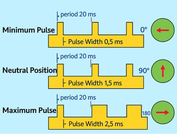
Timing of pulses
The servo is expecting to see this pulse every twenty milliseconds. That means the control system must keep sending it again and again in that time pattern.
The length of the pulse is telling how far we want the motor to turn. So if we take example then we can say one point five millisecond pulse will put the servo at ninety degree position.
Shorter and longer pulses
If the pulse is shorter than one point five millisecond (1.5ms) then it will move the shaft in counter-clockwise direction going toward zero degree position.
But if the pulse is more time than one point five millisecond (1.5ms) then the servo will rotate clockwise until moving toward one hundred eighty degree (180o) position. So now this is how pulse length is making the motor go exactly where we want.
How Servo Motors Hold Position and Work
When these servo motors get a move command then they go to that position and they stay holding in that position.
Now if any outside force tries to push the shaft while it is holding then the servo will fight back and try to not leave that position.
The maximum power it can push back with is called the torque rating of that servo. But it will not hold forever because the position pulse has to keep coming again and again to tell the servo to remain in that same position.
It is important that we first know the technical details and the working method before we decide which servo motor type will be correct for our work.
Types of Servo Motors
Servo motors are made in many kinds of designs, shapes and sizes. The word servo was first used by Joseph Farcot in 1859 when he used steam power for controlling the rudders on a ship.
A complete servo has three main parts which are the motor, the feedback device, and the control electronics.
The servo motor is only one part of this system. For feedback we can use many devices like potentiometer, Hall effect sensor, tachometer, resolver, encoder, linear transducer or any other sensor that is right for our requirement.
The last section of the servo system is the control electronics which runs the motor and compares the feedback data with the command signal to make sure the servo is working correctly. This is the basic idea that explains what actually a servo motor is.
AC and DC Servo Motor Differences
So now we can see that these servo motors are of two main types which are AC and DC. AC servo motors can take bigger current surges and because of this they are used more in industrial machines.
DC servo motors cannot take very high current surges so they are more suitable for smaller works.
Mostly DC types are cheaper compared to AC types. Some servo motors are also made for continuous rotation so we can make our robot move easily with them.
In such motors there are two ball bearings on the output shaft so the friction becomes less and it also becomes easy to reach the potentiometer which adjusts the rest position.
Applications of Servo Motors
When we want to know fully what a servo motor is then we also need to know where we can use them. In radio control airplanes they are used for moving the control surfaces like elevators and rudders. They are also used in walking robots or in robotic grippers.
These motors are small but they have their control circuit already built inside and they can give good amount of power compared to their size.
Servos in Industrial and Harsh Environments
In food industry and medicine making places they are made in such way that they can work in tough conditions where corrosion can happen easily because they are washed many times with high temperature and high pressure to keep strict hygiene.
Servo motors are also used in continuous manufacturing lines where we need same work to be repeated again and again but still with very accurate movement.


Need Help? Please Leave a Comment! We value your input—Kindly keep it relevant to the above topic!