In this post I have explained a simple IC 555 based self optimizing solar battery charger circuit with buck converter circuit that automatically sets and adjusts the charging voltage in response to the fading sunlight conditions, and tries to maintain an optimal charging power for the battery, regardless of the sun ray intensities.
Using a PWM Buck Converter Design
The attached PWM buck converter ensures an efficient conversion so that the panel is never subjected to stressful conditions.
I have already discussed one interesting solar PWM based MPPT type solar charger circuit, the following design may be considered an upgraded version of the same as it includes a buck converter stage making the design even more efficient than the previous counterpart.
Note: Please connect a 1K resistor across pin5 and ground of IC2 for correct functioning of the circuit.
The proposed self optimizing solar battery charger circuit with buck converter circuit may be grasped with the help of the following explanation:
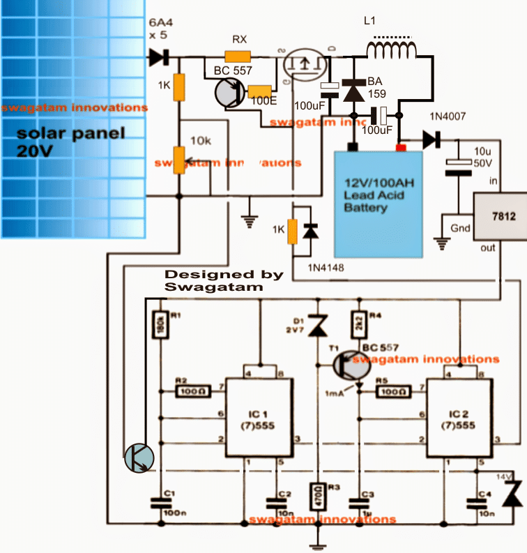
The circuit consists of three basic stages viz: the PWM solar voltage optimizer using couple of IC 555s in the the form of IC1 and IC2, the mosfet PWM current amplifier and the buck converter using L1 and the associated components.
IC1 is rigged to produce a frequency of about 80 Hz while IC2 is configured as a comparator and PWM generator.
The 80 Hz from IC 1 is fed to pin2 of IC2 which utilizes this frequency for manufacturing triangle waves across C1.... which are further compared with the instantaneous potentials at its pin5 for dimensioning the correct PWMs at its pin3.
The pin5 potential as may be seen in the diagram, is derived from the solar panel through a potential divider stage and a BJT common collector stgae.
The preset positioned with this potential divider is initially appropriately adjusted such that at the peak solar panel voltage the output from the buck converter produces the optimal magnitude of voltage suiting the connected battery's charging level.
Once the above is set rest is handled automatically by the IC1/IC2 stage.
During peak sunlight the PWMs get appropriately shortened ensuring minimum stress on the solar panel yet producing the correct optimal voltage for the battery due to the presence of the buck converter stage (a buck boost type of design is the most efficient method of reducing a voltage source without stressing the source parameters)
Now, as the sun light begins diminishing the voltage across the set potential divider also begins to drop proportionately which is detected at pin5 of IC2....on detecting this gradual deterioration of the sample voltage IC2 begins widening the PWMs so that the buck output is able to maintain the required optimal battery charging voltage, this implies that the battery continues to receive the correct amount of power regardless of the sun's retarding illumination.
L1 should be dimensioned appropriately such that it generates the approximate optimal voltage level for the battery when the solar panel is at its peak specification or in other words when the sunlight is in the most favorable position for the solar panel.
RX is introduced for determining and restricting the maximum charging current limit for the battery, it may calculated with the help of the following formula:
Rx = 0.7 x 10 / Battery AH
How to set up the above self optimizing solar battery charger circuit with buck converter circuit.
Suppose a 24 V peak solar panel is selected for charging a 12 V battery, the circuit may be set as instructed below:
Initially do not connect any battery at the output
Connect 24 V from an external C/DC adapter across the points where the solar panel input is required to be fed.
Connect a 12 V for the IC1/IC2 circuit from another AC/DC adapter.
Adjust the potential divider 10k preset until a potential of around 11.8 V is achieved at pin5 of IC2.
Next, through some trial error tweak and optimize the number of turns of L1 until a 14.5 V is measured across the output where the battery is required to be connected.
That's all! the circuit is now set and ready to be used with the intended solar panel for getting an optimized highly efficient PWM buck based charging procedures.
In the above self optimizing solar battery charger circuit with buck converter circuit I have tried to implement and extract an oppositely varying voltage and current output from the the circuit with respect to the sunlight, however a deeper investigation made me realize that actually it should not be responding oppositely rather corresponding to the sun light.
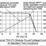
Because in MPpT we want to extract maximum power during the peak hour while also ensuring that the load does not hog the panel and its efficiency.
The following revised diagram now makes a better sense, let's try to analyze the design quickly:
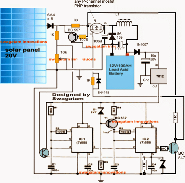
In the above updated design I have made the following important change:
I have added a NPN inverter at pin3 of IC 2 so that now the PWMs from IC 2 influences the mosfet to extract maximum power from the panel and reduces the power gradually as the sun light diminishes.
The PWM pulses along with the buck converter guarantees a perfect compatibility and maximum power extraction from the panel, but diminishes gradually in response to the sun's diminishing intensity.
However, the above set up makes sure about one important aspect, it ensures a balanced input/output power ratio which is always a key issue in MPPT chargers.
Further if in case the load tries to extract an excessive amount of current, the BC557 current limiter immediately comes into action preventing the disruption of the smooth functioning of the MPPT by cutting off power to the load during those periods.
Update
Contemplating the Finalized Design of an MPPT Circuit
After going through rigorous further assessments, I could finally conclude that the second theory discussed above cannot be correct. The first theory makes more sense since an MPPT is meant solely to extract and convert the extra volts into current that may be available from a solar panel.
For example suppose if the solar panel had 10V more than the load specs, then we would want to channelize this extra voltage to the buck converter through PWMs such that the buck converter is able to produce the specified amount of voltage to the load without loading any of the parameters.
In order to implement this, the PWM would need to be proportionately thinner while the sun was at the peak and releasing the extra volts.
However, as the sun power diminished, the PWMs would be required to broaden so that the buck converter was continuously enabled with the optimal amount of power for supplying the load at the specified rate regardless of the sun intensity.
To allow the above procedures to happen smoothly and optimally, the first design appears to be the most appropriate one and the one that could fulfill the above requirement correctly.
Therefore the second design could be simply discarded and the first design finalized as the correct 555 based MPT circuit.
I did not find it appropriate to delete the second design because there are various comments that seems to be linked with the second design, and removing it could make the discussion confusing for the readers, therefore I decided to keep the details as is and clarify the position with this explanation.


Comments
Good evening sir, I have a 96v panel up on my roof, I have bought many controller but without any gain. I want to use the above design, pls I want you to house me on what to do thanks. Johnson
Hello Johnson,
The the above circuit can be difficult to optimize unless you are an expert in this field, therefore I would suggest you to buy an SMPS circuit which are designed to work right from 85 V onward. The output can be as per your required specification, either 12 V or 24 V.
Hello sir, please can i use air core inductor , i couldn’t get ferrite core, if yes how, if no any alternative. thanks
air core will not work, you cannot modify anything in the circuit
Good day sir, i have completed the circuit, which point will i connect the 12v adaptor to set IC1/2 to set it
Hi Pelumi, connect +12V where 7812 connection is connected.
keep pin3 disconnected initially and pin5 from the BC547, test the pin3 pwm by supplying a 0-12V varying input to pin#5 from an external power supply
well done sir, pls can i replace ba159 with in5408, i couldnt get ba 159 diode. thanks
thanks pelumi, no you can’t, because 1n4007 is not a fast recovery diode…you can try any other fast diode such as FR107 etc
Dear Mr. Swagatam,
in order to increase the maximum current switchable by your circuit (5 amps to 10-20 amps), do I only have to buy a larger inductor rated for 20 amps, or do I have to do change something else in your circuit?
I really want to thank you for your great work and support!
Best regards, Sebastian
Dear Sebkov, yes upgrading the inductor should be enough, assuming that the mosfet is already capable of handling that much current.
the inductor specs and the PWM are the two factors that are responsible of determining the current at the output, and ofcourse including the output filter capacitor.
Hello Mr Swagatm thank u agian for ur circuit I just want u to know it is still working fine Sir allowing the panels to work at a better wattage. Keep up the great work Alex. Any more new sine wave circuits please send me a link if there is any sir.
sure Alex, wish you all the best, and keep up the good work
Thank u Mr Swagatam for the design link I will build another one like this and see if it works like ur first I have sir. please remember to send me if any new links on sine wave inverter in ur blog. Thank u
Hello Mr. Alex, thank you so much, I am glad that my concept is working for you and helping you with the desired results.
You can also check out the following article for getting an updated version of the same:
https://www.homemade-circuits.com/2015/11/simple-solar-mppt-circuit-part-2.html
Hello Mr. Swagatam, I am total newbie in electronics – I even hesitated before asking, however I would like to try building this circuit. It does what I would like my solar controller to do – charge 12V battery when there is not enough sun to produce 13.8V. I exactly need it for 20V panel (producing 0.3A in peak sunlight) to charge 7.2Ah sealed lead-acid battery.
The best option for me is to buy a ready circuit somewhere. Could you please tell me sir if this circuit is available for ordering? If not then I will try to make it myself. I have bought Chinese solar controller from ebay, but it is not performing well, so I hesitate to buy from ebay again. I realize it will not be easy to build, but if I get all needed components then soldering should be the easiest part.
First I created a list of all items used in your circuit:
2 x BC 557 [PNP BC557BBK] (T1)
1 x 2V7 2.7V-3V zener diode (D1)
1 x BA 159 (1000V 1A)
2 x 1K
1 x RX (I will use 7.2Ah, so it should be 1k resistor according to given formula)
1 x 10k
1 x 180k (R1)
2 x 100R (R2, R5)
1 x 2k2 (R4)
1 x 470R (R3)
2 x 100uF
1 x 1u
1 x 10u 50V
2 x 10n (C2, C4)
1 x 100n (C1)
1 x L1 (trial & error: 20 turns, 1mm super enameled copper wire over a 1 cm thick ferrite rod)
1 x 1N4007
1 x 1N4148
However following requires some more explanation:
5 x 6A4 (6A 400V) – I was not able to find all 5 rectifying diodes mentioned in the circuit drawing.
1 x 14V (there is some zener diode at bottom-right which states 14V – is it 14V zener diode?)
1 x ??? (there is a NPN transistor bottom left – what parameters should it be?)
1 x switch (there is some switch at the middle top in a circle marked with C, 2 and D – what it is?)
1 x 100E (is it a resistor? 100 ohms?)
1 x 7812 (I suppose it is voltage stabilizer, is any specific parameter needed or these will do? – L7812ABV, L7812CV-DG)
2 x IC (7)555 (IC1, IC2) – will this timer suit? – COM-09273
I will highly appreciate your response sir!
Good sir.
I need simple solar charging controller circuit diagram that can charge solar battery 12volt 100A.
Thanks.
Your blessed
You can try this:
Solar Panel Voltage Regulator Circuit
Hello Ronalds,
the above circuit is a buck converter based MPPT, meaning it will optimize power from a high voltage panel, but if the panel voltage is low this circuit will not perform….
for example it will convert an input power of 24V x 1amp to probably to 14V x 1.71 amps for a 12V battery…but if the panel volt drops to 11V it will not respond.
moreover this circuit not for a newbie, because there could too many adjustments and tweaking which might need an experts knowledge, so it may not be recommended for you..
Sorry a ready made kit is not available from my side.
Hi, I have 40A PWM solar charge controller. I would like to make a 40A mppt solar charge controller, instead of that, can I use a 40A Buck converter output to the existing 40A PWM charger. So that it will work as MPPT. Is it correct? Please share the diagram and components details.
a buck converter is designed to reduce voltage and increase current for a particular load…so what is your load here? example if your input is 12V and you want to charge a 5V battery then a buck converter can be used
Hi Swagatham, I have a 12V, 40A pwm charge controller and I would like to make a 40A buck converter to supply the 15V 40A to the PWM charge controller. Can you please share the required components details and diagram.
Hi Kumar, I am sorry I could not understand your requirement, I think you might have missed something…
What's the function of bc557 and 2.7v zener in pwm pulse generator. Sir irf9540 is not available in our area can u suggest some other MOSFET for the circuit. Shall I use tip 122 instead of MOSFET. Sir I purchased all the components now I am waiting for your reply
BC557/2.7V zener are for providing a constant current for the triangle wave generation so that the PWMs don't get affected at lower voltages.
You can replace the mosfet with a TIP127 (5amps) or TIP147(15 amps) NJTs.
make sure you understand the whole concept thoroughly before attempting it. An researched version of the above is submitted here:
https://www.homemade-circuits.com/2015/11/simple-solar-mppt-circuit-part-2.html
Sir. Shall I change the above buck converter into a buck boost converter in such a way that it should act as a buck converter at peak time more sunshine time and it will act as a boost converter at evening time I hope that due to this arrangement we can charge a battery for long period of time and also that we can convert the extra voltage in peak time into current
Vijay, I don't think the would be effective, because in the evening the current from the panel will also become significantly low which cannot be used for boosting and charging the connected battery…the concept I have explained below is the only way to get the most effective MPPT result
https://www.homemade-circuits.com/2015/11/simple-solar-mppt-circuit-part-2.html
Hi Swagatam,
Small correction in my reply. I removed the mosfet from the ckt and checked. It is in good condition.
Later I learned that PWM works in the same way, it brings down the solar panel voltage down to battery voltage with power loss. That's why good heat sink is required. On the other hand MPPT maintains power all through the charging phase. 🙂
I have purchased 30 A MOSFET today, will try that and let you know about heating problem.
Thanks again.
…I am sorry Sham, I used the wrong name, please ignore it.
Hi Manjunath, if you don't have an inductor (coil) in your circuit, then it cannot be an MPPT or a buck converter based circuit.
and without an inductor your circuit cannot bring down the solar voltage with an MPPT efficiency.
so make sure it has includes an inductor…
Yes you are right Swagatam. Mostfet is gone bad. I see low resistance between all three terminals.
I don't get irf9540, but can arrange irf4905 and try.
No am not using buck converter… I guess it is for powering mcu you mean…
I refered this link for my mcu pwm.
m.instructables.com/id/ARDUINO-SOLAR-CHARGE-CONTROLLER-Version-20/
Sham, sorry but you cannot check and confirm a mosfet with an ohm meter…
Hi Swagatam,
I have rigged up simple P channel PWM charger ckt. I use MCU to control the duty cycle. To be frank, i blindly followed the ckt without understanding it. But its working fine on the first attempt itself, of-course after burning few mosfets. Later added heatsinks to both diode and mosfet.
I have gone through most of the PWM/MPPT chargers you have posted to understand the need of P channel or N channel mosfet.
1. Could you please tell me which is the best type of mosfet to use? N or P channel?
2. If i have to charge a 150 AH battery at C/10 rate, what is the current rating of the mosfet that i need to use? I know that any thing higher value would do but i need to understand the calculation(thumb rule).
3. During charging, if battery voltage is 12.45v My panel voltage reads 13.36 v. and current is at MAX 10.4 Amps. Is it normal? Shouldn't the panel voltage be 19.5 V? (i have 100W x 2 nos connected in parallel)
I hope you will help me in understanding this. Thanks in advance.
Hi Sham,
If the mosfet is getting too hot, and the panel voltage is dropping then your circuit is seriously NOT working…it is in fact doing the opposite.
I don't know whether you used a buck converter or not, but with a buck converter the mosfet is not supposed to get hot and the panel voltage is not supposed to fall below its normal working range.
P or N both are equally good depends on what kind of input is fed…P will respond to negative triggers, and N to positive triggers.
mosfet current rating for a 150AH battery charging could be around 25 Amp t 30 amps….a IRF540 or IRF9540 would do the job
thank u Mr Swagatam i have read the link sir and see it is a trial and error method to determine the right coil. Just a question sir as in our case we have a changing pwm with sun light so would this affect our setting the right frequency to determine the right coil in our mppt sir Alex
Thanks Mr.Alex, changing PWM will not affect the frequency, frequency will always be constant and stick to the original value.
By the way you can also refer to the following updated article:
https://www.homemade-circuits.com/2015/11/simple-solar-mppt-circuit-part-2.html
thank u mr Swagatam i just saw the two articles on buck converter could u send me the last link on the topic sir thank u Alex
Mr Alex, here's the third link:
https://www.homemade-circuits.com/2015/10/calculating-inductor-value-in-smps.html
by tomorrow you may see the new finalized article on MPPT published.
hello Mr Swagatam any thing new on the mppt sir Alex
Mr. Alex, everything is crystal clear now after those three consecutive articles on "Buck", "boost" and "calculating buck inductor" which I posted recently after an exhaustive study…the end formulas have cleared all my doubt and helped me to conclude that the first circuit is indeed the correct one…Ill be soon presenting the details comprehensively through a new article.
yes sir we are always here learning from ur posts
Thanks Alex, you can read the following couple of posts for understanding buck converters:
https://www.homemade-circuits.com/2015/10/how-buck-converter-works.html
https://www.homemade-circuits.com/2015/10/calculate-current-voltage-buck-inductor.html
more will be coming soon.
thank u sir please let us know when this is posted because we all need to get this to work right ALEX
sure alex, please stay tuned
Hello Mr Swagatam i think also the frequency we use maybe should have something to do with the buck converter coil we use but as u say let us see Mr Tonybens design Alex
Hello Alex, higher frequency will allow lower number of turns, and vice versa.
I'll soon be presenting a new article explaining how to design a buck converter coil.
Disha, it won't be a good idea to discuss page on this page, because some of the info on this page could be not precisely correct and only based only assumptions.
To be entirely sure regarding the concept which I tried to implement in the above article you can refer to the following updated new article:
https://www.homemade-circuits.com/2015/11/simple-solar-mppt-circuit-part-2.html
This article has been published after a comprehensive research by me, and is the basic finalized design for achieving an MPPT outcome, if you have any questions you can post it under the above linked article.
@tonny may be this is too late i am commenting as i am going through each of the comments very carefully so i found you mentioned something wrong here so i am correcting here without bothering about later what you have written. As you said that PWM pulse width decreases with decrease in panel o/p voltage and hence even the charging o/p voltage should reduce.Sir it compeletly depends in which context you are speaking about i.e: say if i use a p-channel gate directly connected to pin 3 of IC2 and now say panel voltage drops hence width of PWM reduces i.e p-channel o/p increases(as per pchannel behaviour) and say suppose i used a n-channel gate directly connected to pin 3 of IC2 then what you were mentioning was perhaps correct. That is why if you still want to use n-channel and have same effect as pchannel then a npn transistor is required as already shown. Correct me MR swagatam if wrong
Hi Tonyben,
according to me MPPT is supposed to handle the V x I value and make it stays constant across the panel and the load all the time during day, it does not supposed to have any other role to play. The overload condition is supposed to be monitored and controlled by the error amplifier.
If one succeeds to implement this in an MPPT circuit then I think the mission would be completed.
Hello Swagatam,
In a sense you are right in saying MPPT is not about adjusting an overload. I use an overload scenario to paint the picture clearer.But also look at it this way. if the available power on the panel falls due to diminishing sunshine and the battery load on the controller at that point is greater that the panel power, that is an overload situation.And this situation is what happens all the time with a solar panel. And this is the main reason an mppt is required to match the load to the solar panel for maximum power transfer. Secondly note as long as we have more power on the panels than the load there is actually no mppt because the output power can not be more than what the load demands. So technically speaking mppt only takes when the load power in greater than the input power(solar panel).
Hi Tonyben,
Thanks for the detailed explanation.
However, an MPPT is not about adjusting an overload, an overload control or a short circuit control is the job of an error amplifier, which I have tried to include in the form of the BC557 just beside the mosfet.
The role of MPPT is to maintain the V x I ratio constant even while the sunshine is dropping.
Initially we have the high voltage from the panel on our favor, so we use a narrower PwM because we already have extra power in the form of higher voltage.
Even with the narrow PWM we are able to convert the extra voltage into current and maintain the V x I product constant.
Now when the sun shine goes down, the voltage drops, so to compensate this drop in voltage the PWM is increased so that the buck converter can sustain its output power…this situation goes on until the sun shine has dropped below the maintaining limit.
I'll try to present the scenario with more clarification in the article, and request you all to decide whether or not it's justified and correct.