In this post I have explained a simple IR remote control circuit which can be used for controlling many appliances independently through a single transmitter handset. The idea employs ordinary components like IC LM567, IC 555 and does not incorporate microcontroller devices. The idea was requested by Mr. Saeed Abu and also other dedicated readers of this blog.
Technical Specifications
bro thanks for your reply. Please develop a simple Infrared (IR) Remote Transmitter/Receiver Circuit diagram.
My requirement is:
1) It must be specified for its transmitter. No interference with TV/Vcd remote or any other type of remote.
2) It(receiver) should be powered by Ac 220v.
3) It(receiver) can be used for multiple load (Light+Fan+..+..) by one transmitter
4) Please develop it very simple.

The Design
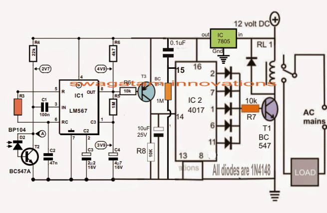
The following design depicts the basic IR receiver module using the IC LM567. The involved stages can be grasped with the help of the following points:
The IC LM567 which is a tone decoder IC or more simply a frequency decoder IC is rigged to produce a particular frequency determined by R3 and C2.
This frequency becomes the bandpass frequency of the circuit such that the circuit now gets locked on this frequency.
The input pin#3 of the IC is attached to a photodiode device for receiving an IR signal which may be tuned to the above set frequency of the IC.
This means that the circuit will now respond whenever D2 detects an IR frequency tuned to the frequency determined by R3/C2 of the configuration.
On detecting a coded frequency from a relevant transmitter the IC M567 output pin8 becomes low and stays in that position until the transmitting signal is prohibited.
Thus this circuit becomes the receiver module and may be triggered by a transmitter circuit tuned at the relevant fixed frequency.
The IC2 which is a Johnsons decoder divider IC is wired as a flip flop circuit, it's integrated to pin8 of the IC LM567.
As long as no signal is detected by D2, pin8 of IC1 remains high, the moment a signal is detected, T3 is triggered, which in turn triggers pin14 of IC2.
The above situation prompts IC2 output to change state thereby either activating RL1 and the connected appliance or deactivating them depending upon its initial condition.
For controlling multiple gadgets using a single transmitter handset, many of the above modules may be constructed and integrated with the corresponding appliances for the intended switching.
Circuit Diagram
Controlling multiple appliances using the following single IR transmitter circuit
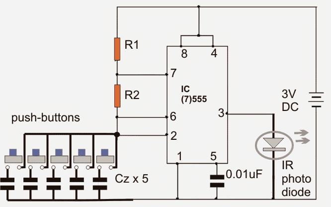
The following circuit forms the transmitter module of the proposed IR remote control for activating multiple gadgets.
It's a simple IC 555 astable circuit, whose output frequency is determined by the 5 individual capacitors and should be appropriately matched with the particular receiver circuit modules as discussed in the above section.
The capacitors attached with the respective buttons should be calculated and matched such that on pressing the relevant button, the corresponding receiver gets triggered for toggling the corresponding appliance.
R1, R2 may be chosen arbitrarily, but Cz must be selected in accordance with the receiver module frequency determined by R3 of the module.
Multiple Frequency Transmitter Circuit


Comments
Sir swagatam,sorry sir,what type and part number of transistor T3? I can't see from your receiver circuit..
Can ordinary photodiode be used in place of bp104
yes any photodiode can be used
thanks dear for uploading my requested circuit.however i request u for ac operated receiver circuit u did not.pls do it also did u check the circuit?
you can use a 12v AC/DC adapter to power the Rx unit…
no I haven't tested it practically.
Dear Swagatam,
As you said in the circuit request:
– It(receiver) should be powered by Ac 220v.
But it is clear form the circuit that the IC need an external 12V DC source ?
How I can do it without external power source or with 220V AC
No, use only a good quality 12V AC/DC 1 amp adapter for supplying the circuit.
Can is use your transformerless power supply circuit that you published in the following link in order to supply this circuit:
https://www.homemade-circuits.com/2012/08/high-current-transformerless-power.html
Dear Ahmed,
Any standard 12V/1amp AC to DC adapter can be employed for powering the circuit
sir, what is the purpose of the 5 buttons?
for toggling 5 appliances separately….
can i change the C2 of main circuit as required? (47nf)
yes you can do, you will need to fix the Tx frequency also accordingly.
F = 1/R3xC2 in this C2 is in uf and R in Ohms isnt it
C2 in Farads, R in Ohms.
Cz capacitors are polarized or non polarized?
since the capacitors will be very small in value, they will be non-polar for sure.
I want make operate 2 relays with two push buttons for curtain motor. request indicate the relevant capacitor and resistor values for my 2 receiver circuits plz
you will have to do it by calculating and also by practical testing through trial and error. I cannot provide the values because the calculated results and practical results could vary and may not precisely match.
can you provide values for R1 R2 and Cz? or let us know how you would calculat these values?
thanks
frequency for each LM567 module may be fixed by using the following formula
F = 1/R3xC2
Accordingly to get a matching set, the relevant capacitor from the 555 may be determined by using a online 555 frequency calculator.
R1 and R2 may be selected as 220K
the idea is to select a slightly different frequency for each Tx/Rx set with each set having an exactly matching frequency, this matching or pairing can be also done by using a frequency meter.
Frequency measuring option is normally available on all digital multimeters.
whats the best way to find the frequency for each component to be controlled? for example and LCD TV, a cable tv box, a bluray player, and a radio? can you provide values for R1 and R2 and Cz?
thanks Swagatam, I think its what i was looking for.
It's my pleasure, Rahul!
good,
i have a couple of 4093 in my box,
so i can just make this circuit.
thank you..
I follow you with great passion…
regards
andrea
that's great Andrea! thanks
dear swagatam,
thank you for your help.
can you tell me if i can to use another IC instead the 4017.
in this moment i haven't this component.
thank you so much
regards andrea
dear andrea,
you can replace the 4017 circuit entirely with 4093 flip flop, you can refer to it in the following article
https://www.homemade-circuits.com/2011/12/build-these-simple-flip-flop-circuits.html
dear swagatam,
seen that the 4017 is connect as an flip flop, it can be replaced with another IC for example the IC 4047 or ne555?
for to activate more appliances i must to built more received circuit of first diagram?
on the first diagram the value of R3 depend from the frequency for set, but in that order of values?
d1-d6 can i use 1n4148 or what other type?
thank you so much
best regards
andrea
dear Andrea,
no, 4047 or 555 cannot be used for 4017
yes more receivers for more appliances
R3 will need to be made different for different receivers
d1-d6 = 1N4148
Hi Swagatam
For an astable 555 vibrator, the timer will oscillate only when the timing capacitor is connected. The momentary connection due to the pressing of the push button will allow the oscillation momentarily…….in practical there will be oscillation for only a fraction of a second or no oscillation. And I wonder, if that momentary oscillation will trigger the receiver module.
Hi Abu-Hafss,
yes momentary connection is what we want from the transmitter…if it's pointed correctly toward the receiver, the response will be instant, moreover the user has the option of keeping the button pressed for a few seconds until the receiver responds