In this post I have explained about a circuit which can be used to monitor and detect the presence of municipal water supply by operating a pump motor through an intermittent ON/OFF timer.
The timer keeps the pump motor ON for 15 seconds, if water is not detected, the pump is switched OFF for the next 15 minutes. After 15 minutes it repeats the water detection process, and this goes on until water is finally detected in the pipe.
Once water is detected, the timer is disabled and the pump motor is allowed to run continuously as long as the water supply is available.
The idea was requested by Mr. Aslam Iqbal, as I have explained below.
Circuit Objective
I need help constructing a circuit that controls a water pump using sensor probes and a relay timer. The pump should be activated every after 15 minutes, for a brief duration of 10-15 seconds through a preset timer relay. However, in case the sensor probes detect water flow, the pump should continue to run. After the first 10 to 15 seconds, the pump should automatically turn off if the water in the pipe becomes unavailable.
Circuit Description
If you do not want to read the following description, you can watch the following video instead:
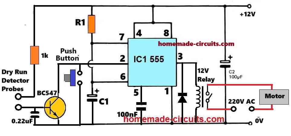
Referring to the diagram below, the working of the proposed Pump Motor Timer Circuit with Dry Run Protection circuit can be understood with the following points:
The heart of the circuit is the IC 555 which is configured as a standard astable multivibrator circuit with a PWM control.
In this mode the IC 555 generates a square wave output, with an ON and OFF timer periods of around 15 minutes, which are individually adjustable using the pot RV1.
Here, the pot VR1 adjusts the output PWM to fine-tune the 15 minutes ON/OFF time to 15 seconds OFF and 15 seconds ON time, at the IC output.
Alternatively, you can also manipulate the values of the R1 and R2 to adjust the above duty cycle of the 555 output.
The relay connected with the output pin#3 of the IC555 responds to these set ON/OFF periods and keeps its contacts turned ON for 15 seconds and turned OFF for 15 minutes.
As a result, the attached motor remains switched ON for every 15 seconds and switched OFF for 15 minutes, as long as it is in the powered condition.
This takes care of the pump motor's ON/OFF switching cycle while it detects the availability of water in the municipal pipeline.
In an event water supply becomes available in the pipe, it is quickly detected by the sensor probes introduced across the relevant area of the pipe.
As soon as water bridges the probes, the +12V supply reaches the base of the T1 BC547 transistor, which instantly conducts and grounds the pin#2/6 of the IC 555.
Due to this the IC 555 is inhibited from its astable mode, causing a permanent logic high at its output pin#3.
This logic high locks the relay ON and the motor pump now starts operating without switching OFF, pumping out the available water supply from the source.
This goes on as long as water supply is available in the pipe line.
When water supply stops and becomes unavailable, the water across the probes is removed.
This causes the T1 BC547 to turn OFF, restoring the IC 555 back to its astable mode.
The IC 555 output now keeps the relay and motor operational for another 15 seconds and then turns it OFF.
After this, the 15 second ON and 15 minutes ON cycle timing cycle of the IC and motor starts repeating yet again.

Using Push Button to Manually Start the Motor
If you are not interested in the above automatic switching of the motor pump and wish to implement a manual push button start, you can try the following concept:
How the Circuit Works
Here, the IC 5-5-5 is configured as a monostable timer for activating the pump motor for a predetermined duration, as set by the values of the R1 and C1 timing components.
In this pump motor controller circuit, the motor is started or switched ON manually by the user by pressing the given push-to-on switch.
This activates the IC monostable timer causing its pin#3 to become high, so that the attached relay is activated. The relay now switches ON the pump motor.
Once switched on, the water pump looks for the availability of water in the pipe or the source. If water supply is detected, the pump starts drawing water into the tank.
If water is not detected within the predetermined period, the monostable time elapses turning of the IC, which in turn switches off the relay and the pump.
This feature takes care of the dry run issue, and never allows the pump motor to remain operational during an absence of water in the pipe.
In case water is detected, the pump motor starts drawing water and this water supply from the pump now bridges the dry-run detection probes.
Due to this, the BC547 transistor is switched ON, which then grounds the pin#2 of the IC, bypassing the timing components of the IC.
As a result, the output of the IC and the relay are permanently turned on, and the pump motor continues to draw water as long as the water remains available from the source.
As soon as the water supply at the source becomes unavailable, the water across the dry run detector probes is removed, which enables the monostable-timer back into action, causing the motor to remain operational for some moments until the monostable time has elapsed, and then the motor pump is automatically turned off.
Parts List
- All resistors are 1/4 watt CFR
- 470k, 330k, 1k = 1 each
- Potentiometer 10k = 1
- Capacitors
- 47uF or 100uF / 25V Electrolytic = 1
- 0.22uF ceramic = 1
- 100nF Ceramic = 1
- 2200uF / 25V = 1
- Semiconductors
- IC 555 = 1
- Transistor BC547 = 1
- Diode 1N4007 = 1
- Relay 12V 40 amp = 1


Comments
Hi Of your above circuit i would like to start the motor not by pushing the switch But by automatic Dusk sensing using LDR , Can you please suggest the changes and snd me a redrawn circuit.
Your reply is very much appreciated
Thank you
H Reddy
Sure, here’s the modified desgn you can try:

In push button operated dry motor pump circuit what’s value of R1 &C1 Timing component
That will depend on how long you want the motor to remain switched ON.
You can calculate it using the following calculator:
https://www.homemade-circuits.com/ic-555-timer-monostable-circuit-calculator-software/
Also, what is the value of R1 and C1 in ddiagram 2
You can use these calculators:
https://www.homemade-circuits.com/ic-555-timer-astable-circuit-calculator/
https://www.homemade-circuits.com/ic-555-timer-monostable-circuit-calculator-software/
If I want to trigger the motor when the wires are placed at 75% height and I want the pump to drain the whole thing, how will it be done? Because, according to your logic, as soon as the timer is disabled the motor will run, but as soon as the water level is below the 75% mark, it stops
The above circuit was designed as per the specific request of the user, it will not fulfil your requirement.
You can try the following concepts instead:
https://www.homemade-circuits.com/how-to-make-simple-water-level/
I want a pcb circuit design for the above project
Can we directly connect a 5v (DC) water pump to pin 3 of 555 and gnd
If the pump current rating is less than 100mA then, yes…
Can a water pump be employed instead of the relay,AC supply and motor
The relay is used for switching the motor pump ON/OFF, without a relay that will not be possible….
When the power supply is 12 volts 500 MA, often the relay chatters when the load is the pump; what is the suggested ampere for the power transformer for the 40A relay?
The relay coil current requirement may not be more than 100mA, so 500mA trafo is OK.
The chattering can be stopped by adding a 220uF/25 capacitor right across the relay coil.
Also make sure the power supply DC has a large filter capacitor of around 2200uF/50V
I do not need the timer. I just want that the pump should stop when the tank is out of water. Accordingly, please modify the circuit.
You can try the first circuit from this article:
https://www.homemade-circuits.com/municipal-water-supply-sensor-pump/
The circuit is very good, but the problem is that the probes oxidize with electrolysis.
You can employ one of the ideas explained explained in the following article, to solve the corrosion problem:
https://www.homemade-circuits.com/anti-corrosion-probes-for-water-level/
COULD FLOAT SWITCH BE USED AS THE SENSING PROBE
Sure, you can use any type of sensor which can detect water and conduct voltage.
Hello
It is a very interesting circuit.butI think it is better to amplify the IC output with a transistor before connecting it to the relay in order to increase the current. Also, a filter should be prepared to remove the noise of AC motors Thanks
Amir Saraf
Hi, thanks for the suggestion.
However, the IC 555 can handle upto 200mA current at its pin#3, so a 40 amp relay which might have a coil resistance of 100 Ohms can be easily handled by the 555 without any transistor.
Hi
Thank you for your attention and response to my suggestion. In any case, the output has always been sensitive and not protected, so the output of the IC can provide the necessary current to move the relay, it is not bad if the output is shielded in some way.
Thanks
Sure, If you are not comfortable with the direct relay connection with pin#3 of the IC, you can add a transistor stage for the relay at pin#3, for extra safety.
I am thankful for your prompt response on my specific need. Hope there may some users as well needing this circuit.
With a feeling of proudness by way of your generosity and being naive on electronics, may I as ask, if possible, in this circuit, motor should also turn off when tank is full? I think it is possible with a little variation in the same circuit by adding a probe of tank full sensor.
You are welcome.
The full tank motor auto switch off can be implemented by driving the relay through a transistor at pin#3 and then adding another BJT between the base and ground of the driver transistor. Then the base of this BJT can be configured with the probes for detecting the fully tank level.
This will allow the motor to shut off as soon as the tank is full, however when the tank water drops below the probes, the motor will again start searching for water, which can be a problem.
So the new water level controller should be set in way that once it turns off the motor, it should not switch ON the motor until the water level has dropped below a certain lower level.
Implementing the above might require a separate water level controller circuit.
Hello, everybody!
I don’t see the point of periodically checking to see if the water supply is available. If the sensor is in the water, the pump should be switched on. If there is no water, the sensor is not in the water, so the pump is switched off.
I propose my variant of the scheme. The schematic can be downloaded from this link:
https://www.homemade-circuits.com/wp-content/uploads/2024/05/water-level-controller-compressed.jpg
———
220V electric pump control, simple automation circuit on two transistors
———
DP1 is a sensor of water level in the tank to be filled. If tank is not full DP2 contacts are closed and through them the voltage goes to the base of transistor VT 1. The key on the compound transistor VT1-VT2 opens and switches on the current to the relay winding K1, its contacts switch on the power supply to the pump. When the tank is full, the float of the sensor DP1 rises and its contacts open. The voltage is no longer supplied to the base of VT1. The key on the compound transistor VT 1-VT2 closes and switches off the current to the relay winding K1, its contacts switch off the power supply to the pump.
DP2 is the water level sensor in the well. If the water level is sufficient for normal operation of the pump, the sensor contacts are open and the operation of the key on transistors VT 1 and VT2 is not affected.
If the water level in the well is insufficient for normal operation of the pump, the DP2 sensor contacts are closed and shunt the base of transistor VT 1, shorting it to the minus supply. As a result, the transistor key VT1-VT2 remains closed regardless of the state of the DP1 sensor contacts. This will prohibit the pump from starting until there is enough water in the well for safe operation of the pump.
Parts
Relay K1 type BJ-118-1C. This is a relay with a 12V winding and 5A contacts at 230V. The relay can be replaced by another relay with 12V winding or other voltage.
If the winding is not on 12V, then accordingly the supply voltage of the circuit must be different, – such as the nominal voltage of the relay winding. Capacitor C1 should be of voltage not lower than the supply voltage.