In this post I am going to explain pull-Up resistor and pull-down resistor, why they are commonly used in electronic circuits, what happens to electronic circuits without Pull-Up or Pull-down resistor, and How to calculate Pull-Up and Pull-down resistor values and finally we will see about open collector configuration.
How Logic Inputs and Outputs Work in Digital Circuits
In digital electronics and most microcontroller based circuits the involved digital signals are processed in the form of logic1 or logic0, i.e. “HIGH” or “LOW”.
Digital logic gates become the fundamental units of any digital circuit, and by utilizing “AND”, “OR” and “NOT” gate we are able to build complex circuits, however as noted above digital gates can accept only two voltage levels which “HIGH” and “LOW”.
The “HIGH” and “LOW” are generally in the form of 5V and 0V respectively. “HIGH” is also referred as “1” or positive signal of the supply and “LOW” is also referred as “0” or negative signal of the supply.
Problems arise in a logic circuit or a microcontroller when the fed input is somewhere in the undefined region between 2V and 0V.
In such a situation a logic circuits or microcontroller may not recognize the signal properly, and the circuit will make some wrong assumptions and execute.
Generally a logic gate can recognize the signal as “LOW” if the input is below 0.8V and can recognize the signal as “HIGH” if the input is above 2V. For microcontrollers this can actually vary a lot.
Undefined Input Logic Levels
The problems arise when the signal is between 0.8V and 2V and varies randomly at the input pins, this issue can be explained with an example circuit using a switch connected to an IC or a microcontroller.
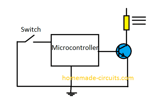
Assume a circuit using a microcontroller or an IC, if we close the circuit, the input pin goes “LOW” and the relay turns “ON”.
If we open the switch, the relay should turn “OFF” right? Well not really.
We know that the digital ICs and digital microcontrollers only takes input as either “HIGH” or “LOW”, when we open the switch, the input pin is just open circuited. It is neither “HIGH” nor “LOW”.
The input pin must be “HIGH” in order to turn the relay off, but in the open situation this pin becomes vulnerable to stray pickups, stray static charges, and other electrical noise from surrounding, which can cause the relay to go ON and OFF randomly.
To prevent such random triggers due to stray voltage, in this example it becomes mandatory to tie the shown digital input pin to a “HIGH” logic, so that when the switch is flipped off, the pin automatically connects to a defined state “HIGH” or the positive supply level of the IC.
To keep the pin “HIGH” we can connect the input pin to Vcc.
In the below circuit the input pin is connected to Vcc, which keeps the input “HIGH” if we open the switch, which prevents random triggering of the relay.
You may think, now we have the solution worked out. But no....not yet!
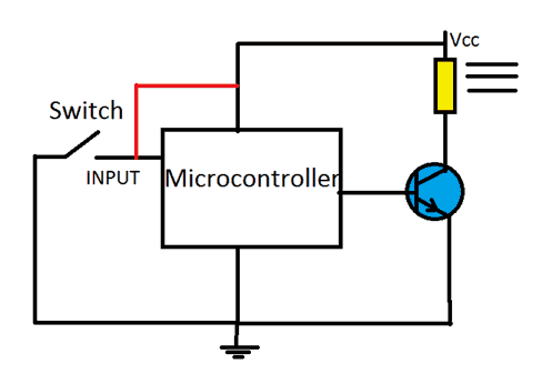
As per the diagram if we close the switch there will be short circuit and shut off and short circuit the whole system. Your circuit can never have any worst situation than a short circuit.
The short circuit is due to very large current flowing through a low resistance path which burns the PCB traces, blowing of fuse, triggering safety switches and even may cause fatal damage to your circuit.
To prevent such heavy current flow and also to keep the input pin in “HIGH” condition, we can utilize a resistor which is connected to Vcc, that is between the "red line".
In this situation the pin will be in a “HIGH” state if we open the switch, and on closing the switch there won’t be any short circuit, and also the input pin is allowed to directly connect with the GND, making it “LOW”.
If we close the switch there will be negligible voltage drop via the pull-Up resistor and rest of the circuit will remain unaffected.
One must choose the Pull-Up / Pull-Down resistor value optimally so that it won’t draw excess through the resistor.
Calculating Pull-Up Resistor value:
To calculate an optimum value, we have to know 3 parameters: 1) Vcc 2) Minimum threshold input voltage which can guarantee to make the output “HIGH” 3) High level input current (The required current). All these data are mentioned in the datasheet.
Let’s take the example of logic NAND gate. According to its datasheet Vcc is 5V, minimum threshold input voltage (High level Input voltage VIH) is 2V and High level input current (IIH) is 40 uA.
By applying ohm’s law we can find the correct resistor value.
R = Vcc - VIH (MIN) / IIH
Where,
Vcc is the operating voltage,
VIH (MIN) is HIGH Level Input voltage,
IIH is the HIGH Level Input Current.
Now let’s do the matching,
R = 5 - 2 / 40 x 10^-6 = 75K ohm.
We can use a resistor value maximum of 75K ohm.
NOTE:
This value is calculated for ideal conditions, but we don’t live in an ideal world. For best operation you may connect a resistor slightly lower than calculated value say 70K, 65k or even 50K ohm but don’t reduce the resistance low enough that it will conduct huge current for example 100 ohm, 220 ohm for the above example.
Multiple gate Pull-Up resistors
In the above example, we saw how to pick a Pull-up resistor for one gate. What If we have 10 gates which all are need to be connected to Pull-Up resistor?
One of the ways is to connect 10 Pull-Up resistors at each of the gate, but this isn’t cost effective and easy solution. The best solution would be connecting all the input pins together to single Pull-Up resistor.
To calculate the Pull-Up resistor value for the above condition follow the formula below:
R = Vcc - VIH (MIN) / N x IIH
The “N” is the number of gates.
You will notice that the above formula is the same as the previous one; the only difference is multiplying the number of gates.
So, let’s do the math again,
R = 5 -2 / 10 x 40 x 10^-6 = 7.5K ohm (maximum)
Now for the 10 NAND gates, we got the resistor value in a way that the current is 10 times higher than one NAND gate (In previous example), so that the resistor can maintain minimum of 2V at peak load, which can guarantee the required output without any error.
You can use the same formula for calculating Pull-Up resistor for any application.
Pull-Down Resistors:
The Pull-Up resistor keeps the pin “HIGH” if no input is connected; with Pull-down resistor, it keeps the pin “LOW” if no input is connected.
The pull-down resistor is made by connecting the resistor to ground instead of Vcc.
The Pull-Down can be calculated by:
R = VIL (MAX) / IIL
Where,
VIL (MAX) is LOW level input voltage.
IIL is LOW level input current.
All these parameters are mentioned in the datasheet.
R = 0.8 / 1.6 x 10 ^-3 = 0.5K ohm
We can use maximum of 500 ohm resistor for Pull-down.
But again, we should use a resistor value less than 500 ohms.
Open collector output / Open Drain:
We can say a pin is “open collector output” when the IC can’t drive the output “HIGH” but can only drive its output “LOW”. It simply connects the output to the ground or disconnect from ground.
We can see how the open collector configuration is made in an IC.
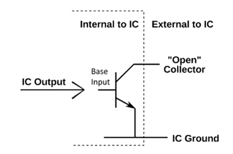
Since the output is either ground or open circuit, we need to connect an external Pull-Up resistor which can turn the pin “HIGH” when the transistor is OFF.
This is same for Open drain; the only difference is that the internal transistor inside the IC is a MOSFET.
Now, you may ask why do we need an open drain configuration? We need to connect a Pull-Up resistor anyway.
Well, the output voltage can be varied by choosing different resistor values at the open collector output, so it gives more flexibility for the load. We can connect load at output which has higher or lower operating voltage.
If we had a fixed pull-up resistor value we can’t control the voltage at the output.
One disadvantage of this configuration is that, it consumes huge current and may not be battery friendly, it need higher current for its correct operation.
Let’s take example of IC 7401 open drain logic “NAND” gate and see how to calculate pull-up resistor value.
We need to know the following parameters:
VOL(MAX) which is the maximum input voltage to IC 7401 which can guarantee to turn the output “LOW” (0.4V).
IOL(MAX) which is the Low level input current (16mA).
Vcc is the operating voltage which is 5V.
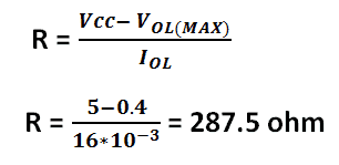
So, we here we can connect a Pull-Up resistor value around 287 ohm.
Have any questions? Please use the comment box below to express your thoughts, your queries will be replied ASAP

Comments
How to rewire xl6009 with pull up pull down on a xl6009 buck booster ? Where coul I find a diagram ?
Why would you need a pull up or pull down resistor in xl6009?