In this post I am going to explain the datasheet of PIR or Pyroelectric Infrared Radial Sensor HC-SR501. We will understand for what purpose PIR sensor is used? Its basic trigger operations, pin connection details, technical specifications and finally we will be looking at some real life applications.
We will begin by understanding the actual PIR sensor unit which are installed inside standard PIR modules and learn its internal characteristics, pinout details and internal working details.
What is a PIR Sensor?
PIR stands for Pyroelectic Infrared Radial Sensor or Passive Infrared Sensor. PIR is an electronic sensor which detects the changes in the infrared light across certain distance and gives out an electrical signal at its output in response to a detected IR signal. It can detect any infrared emitting object such as human beings or animals if it is the range of the sensor, or moves away from the range, or moves within the range of the sensor.
The PIR sensor module can be divided in to two parts an infrared sensitive crystal and the processing circuit.
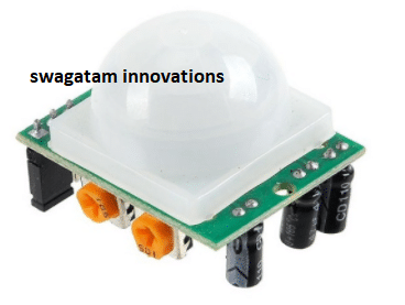
Illustration of PIR sensitive crystal:
The dark portion of the metal where the IR sensitive crystal is housed, the sensitive crystal can detect the level of infrared in the surroundings. It actually houses two pyroelectic sensors for detecting moving objects. If one of the sensitive crystals detects change in infrared (increment or decrement) than the other sensitive crystal, the output gets triggered.
A dome shaped plastic structure is normally placed over this sensitive crystal which acts as lens to focus the infrared light on the sensors.
How PIR Works
The sensing operation of a pyroelectric infrared sensor is based on the property or characteristic which becomes responsible for altering the polarization of its material in response to temperature changes.
These sensors employ a dual or a pair of sensing elements for sensing the IR signals in two steps, which ensures a foolproof detection by cancelling the unwanted temperature variations within the existing EMI stage. This two-step sensing process improves the overall stability of the sensor and helps to detect IR signals only from human presence.
When a human being or a relevant IR source moves past a PIR sensor, the radiation cuts into the pair of sensing elements in an alternate manner, triggering the output to generate a pair of ON/OFF or high and low pulses, as depicted in the following waveform:
The following rough Gif simulation shows how a PIR sensor responds to a moving human and develops a couple of short sharp pulses across its output leads for the required processing or triggering an appropriately configured relay stage

Internal Layout of a PIR
The following figure shows the internal layout or the configuration inside a standard PIR sensor.
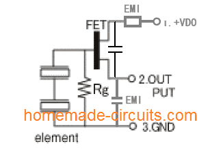
On the left we can see a pair of IR sensing elements connected in series. The upper end of this series is connected with the gate of an in-built FET which acts as a small IR signal amplifier. The Rg pull down resistor provides the required standby zero logic to the FET to makes sure that it stays completely switched OFF in the absence of an IR signal.
When a moving IR signal is detected by the pair of sensing elements, it generates a corresponding pair of hi and low logic signals as discussed above:
These pulses are appropriately amplified by the FET and replicated at its output pin for further processing by an attached circuitry.
The associated EMI stages along with the capacitor provide extra filtration to the process, in order to produce a clean set of pulses at the indicated output pin of the PIR.
Testing Set Up for the PIR Sensor
The following image shows a standard PIR sensor test set up. The output and Vss pins (negative pin) of the PIR is connected with an external pull down resistor, the Vdd pin is supplied with a 5V supply.
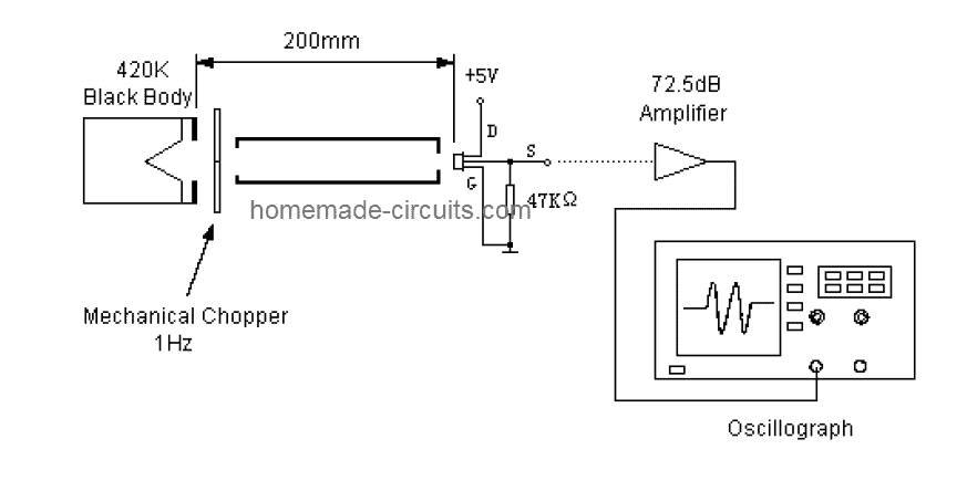
A stationery black body generates the required equivalent infrared radiation for the PIR sensor through a chopper mechanism. The chopper plate alternately cuts the IR signals imitating a moving IR target.
This chopped IR signal hits the PIR sensor generating the specified pulses across its output pin, which is suitably amplified through an opamp for analysis on a scope.
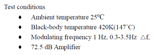
The Ideal Test Conditions for the above set up can be seen below:
Balancing the Sensing Element output
Since a dual sensing mechanism is employed in PIRs, it becomes necessary to ensure that the processing through the pair of lenses is correctly balanced.
The sensing elements are tested and appropriately configured by evaluating the respective single signal output voltage (SSOV) through the following formula:
Balance: |Va – Vb| / (Va + Vb) x 100%
Where, Va = Sensitivity of side A (mV peak to peak)
Vb = Sensitivity side B (mV peak to peak)
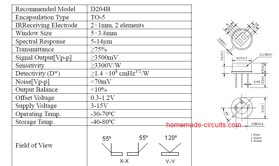
Main Specifications
The main technical specifications and dimension parameters of a PIR sensor can be learned from the following details:
Using PIR Inside Modules
Today you will find PIR modules having a PIR sensor integrated with specialized processing circuit and lens. This enhances the performance of the PIR many folds and allows the end user to get well defined optimized, amplified output from the module.
This output now only needs to be configured with a relay stage for the required ON/OFF switching of a load in response to a human presence across the stipulated zone.
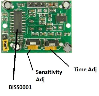
The circuit inside standard modules consist of IC BISS0001 which is specifically designed for motion detection applications. Two knobs are provided, one for adjusting the sensitivity of the module and another knob is for adjusting the time length for how long the output should stay HIGH after the module is triggered.
Now let’s investigate the technical details of the PIR sensor HC-SR501.
Operating Voltage:
The HC-SR501 is from 5 V to 20 V, which makes great flexibility for circuit designers.
Current consumption:
The HC-SR501 is a battery friendly device; its current consumption is 65 mA when it detects any change in IR light.
Output Voltage:
When the module detects a motion of infrared the output goes HIGH at 3.3 V, if the module detects no motion it goes LOW or 0 V after a fixed period.
Delay time:
A knob is provided to adjust the time for the output to stay HIGH after detecting the IR. This is time period can be adjusted from 5 seconds to 5 minute.
Sensitivity Range:
The angle of the detection area is around 110 degree cone. A knob is given to adjust the sensitivity; we can vary from 3 meter to 7 meters perpendicular to senor. The sensitivity reduces as we move either sides of the sensor.
Operating Temperature:
The HC-SR501 has an impressive operating temperature ranging from -15 to +70 degree Celsius.
Quiescent current:
The Quiescent current is the current consumed from the supply, when the sensor is not detecting any motion or when it is in idle. It consumes less than 50 uA, which makes the sensor battery friendly.
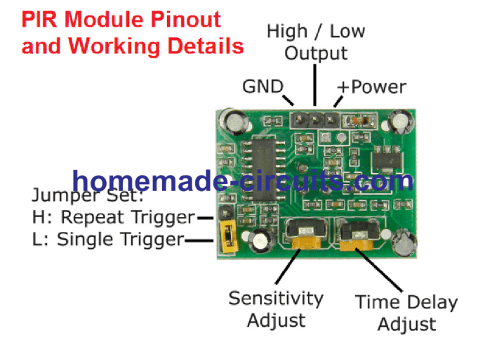
Trigger modes:
The PIR module has two trigger modes: Single trigger / non-repeat mode and repeat trigger. These two modes can be access by changing the jumper position given in the module.
Single Trigger Mode / Non-repeat Mode:
When the PIR sensor is set in single trigger mode (and the timer knob / delay time is set for 5 seconds (say)), when a human is detected the output turns HIGH for 5 seconds and turns LOW.
Repeat Trigger Mode:
When the PIR sensor is set in repeat trigger mode, when a human is detected the output turns HIGH the timer counts for 5 seconds, but when another human is detected with in those 5 seconds the timer reset to zero and counts another 5 seconds after 2nd human is detected.
Block Time:
The block time is the time interval where the sensor is disabled or will not detect motion. The block time for HC-
SR501 is 3 seconds by default.
This occurs after the delay time (which was set by timer knob) the output goes LOW for 3 seconds; during this interval no motion will be detected. After the 3 seconds (LOW) the sensor will be ready to detect motion again.
In other words, when the sensor detects motion the output goes HIGH, the output remains HIGH as per the timer knob (say 5 seconds), after 5 seconds the PIR sensor goes LOW, the LOW signal will remain for 3 seconds regardless of the new motion if any.
Dimensions of the module:
The sensor is compact enough to hide from people’s view so that it won’t affect decorates etc. It measures 32 mm x 24 mm.
Lens Size:
The white dome structure which encloses the pyroelectric sensor is called Fresnel lenses, which increase the detection range and it looks opaque. It measures 23 mm in diameter.
Applications:
• Security systems.
• Automatic lights.
• Industrial Automaton Control.
• Automatic doors.
You can find some of the projects using PIR sensor in this site.
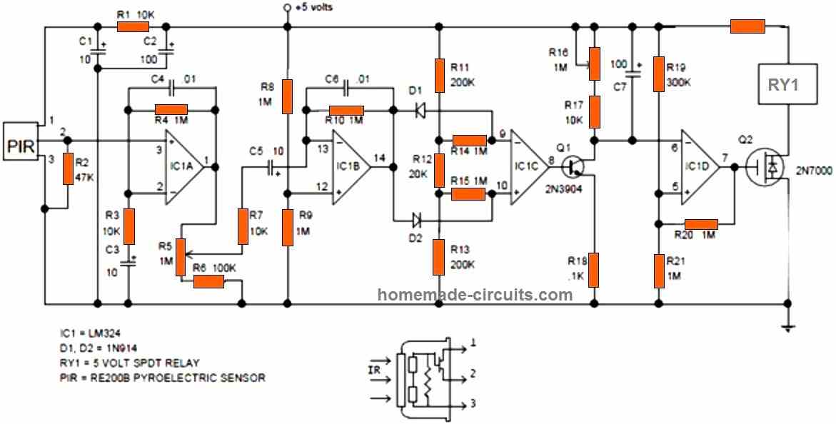
Typical PIR Module Internal Circuit Diagram
For enthusiasts who intend to build the complete PIR module along with the sensor and a full fledged amplifier, the following standard PIR schematic can be employed and used for any relevant PIR sensor based application triggering.
Have further doubts or questions? Please feel free to put them forth through the below given comment box

Questions & Answers
I have PIR “1byone” (3 off) paired to a single radio receiver & alarm siren. One now fails to work. I believe the 8pin SMT chip has failed as PIR input to it is raised to 3.5V but nothing comes out. The trigger to Tx should also light LED but doesn’t. The chip type is NT619 but I cannot identify it, {In order to replace it}. It may be an OP-Amp but that could not encode (ASK) could it? I wonder how this can be done so simply.
I am retired electronics engineer. I can solder – have instruments – but don’t know it all…. ! These PIRs have to be “learned” by the receiver BUT this is the only IC in the circuit. I have a photo of PCB but seem unable to post it here…? There are 3 transistors which check OK, a 3.5V regulator, and a SAW for the TX. (Maybe 330 or 430Mhz).
I am unable to just buy a replacement as gone off the market in UK. Any help would be gratefully received.
Yes, PIR modules can be quite unpredictable sometimes.
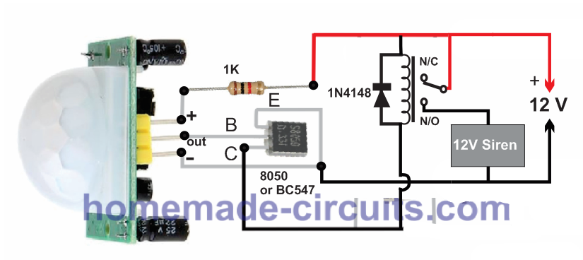
For me the following configurations has always worked flawlessly without any issues, so you can try this configuration. Just watch the transistor polarity. If you use BC547 for the transistor make sure to swap the collector/emitter pins in your design:
@Ghulam mohio din These cheap microwave sensors sense on BOTH sides of the sensor. Can’t isolate the sensing. Someone moves in the room next door …
Very good and detailed helpful article. SIR what about microwave radar human sensor, which one is best PIR or Microwave human body sensor)? And also please guide me if i want to use RCWL-0516 microwave human body sensor then how to increase the on time in proper way? I tried with 1uf capacitor at c-e point but i am feeling its not proper work with direct soldering. So please guide me how to assemble plz
Thanks
Thank you Ghulam!
I have not studied RCWL-0516 microwave sensor yet, let me study it thoroughly, then if possible I will try to create a new article on it with all the details.
I think PIR is much easier to build and configure and maybe its cheaper. A PIR is also very sensitive to human movement detection
Since I have not used a microwave human sensor practically, i cannot confirm which one is better!
Sir i watched vedio on yoitube, as per youtube microwave sensor not required to fix outside, it can detect from inaide the box….and detection is better than pir, plz give me proper solution
Ghulam, yes microwave radar can detect human even from behind an opaque barrier, but the barrier thickness should be thin, otherwise it may not detect correctly.
In that case a microwave doppler sensor appears to be more efficient than a PIR sensor.
I think you should try the RCWL-0516 and let me how it goes.
Need help in making a intruder alarm using laser module or PIR. My knowledge in electronics is fairly outdated. Did my training about 50 years ago, mainly in thermionic valves (vacuum tubes) and on equipment used during WWII.
No problem, you can try the circuit which is explained in the following article. In the circuit the transistor is an 8050, so make sure to check the pinouts correctly if you want to use any other transistor such as a BC547:
https://www.homemade-circuits.com/pir-burglar-alarm-circuit/
Very good, comprehensive, and useful article.
Thank you very mush dear swagatam
truly
Ali
Thank you so much Dear Ali, I am glad you found the post helpful…
Hey, I’d like to install a proximity sensor in my car that sets of a quick 1 second warning siren to deter any would be car prowlers. I’ve seen the kits online but they don’t make it completely clear how to install. Also I’d like to make the radius roughly an 1-2 foot perimeter on the outside of my vehicle. Is this possible, or are these sensors limited by glass/walls etc?
Hello Haj, If it’s still interesting for you, why not use a PIR sensor, priced at $4-7 per unit, as a switch for the overhead light in your vehicle’s cabin? To install the PIR sensor, place it near or inside a vehicle lantern, then simply leave the standard light switch in the ON position. When you exit your vehicle, any visitors will be illuminated as the vehicle’s door opens. This will provide you with nighttime silence and a good opportunity to capture the face of a potential intruder with a video recorder. In Russia, it is illegal, but sometimes people resort to this method against very offensive visitors – placing one or more pillows with a 5-10cm thickness and vertically embedded fisherman’s hooks or small narrow blades inside them on the seats. Such pillows can potentially cause harm or even be lethal – a serious crime and morally wrong. I’m sharing this as a warning so that you won’t become a victim of the same tactics.
Sure, you can try installing the following circuit. You can fix it near the dashboard of the car. However, the PIR will not be able to detect an intruder through a metal obstruction, but it will be able to detect through a glass window.
https://www.homemade-circuits.com/pir-burglar-alarm-circuit/
What is the function of the potentiometers R5 and R16.
R5 seems to be the sensitivity control and R16 could be the delay control.
This system is not good , repeat time 3 seconds is bad ,how to set 0 second ?
Very good article.
Although I think I can solve it, you would save me time if you have the scheme of a penumbra detector applied to the HC-SR501 (obviously to activate it in certain conditions (level) of light)
I confess that I have just discovered you and I am sure that I will explore other projects of your authorship
Thanks and regards
Thank you for liking the article, and I appreciate your generous feedback…
I don’t think penumbra can be detected using a PIR, since PIR will detect only IR radiation and not shadows. It can probably be done using an LDR window comparator circuit.
hi i can’t solve this problem: once i connect the pir motion sensor with a valid program and i try to light up a led only when the sensor detects motion, my sensor always detects motion and the led is always on. The program is also right because I compared it with people who are better than myself for the circuit
Hi, without seeing your PIR connections it willbe difficult for me to solve the problem….
Alternatively, you can try mounting the PIR output transistor directly on the PIR pins as shown in the following example, and check the results:
Hallo!
I have several PIR LED solar burglar lights and a few of them lightens up now and then without any reason; what can I do to minimize false “firing”?
Thanks in advance for any answer!
Best regards,
A. Fakkers.
Hi, try cleaning the whole system and the associated PCB with ethyl alcohol, and check the response again….make sure the PIR see no temperature emitting object within its range
Sir, I am fan of your Facebook page. Nice article.
I want to reduce the delay time from 5 seconds to 1 second ?
How ?
I have integrated this to a water flow pipe ( where people wash/sanitize as they walk in the apartment ) as soon as someone walks in.
The thing is – after the person moves out of range, the water still keeps flowing for the next 5 seconds.
That’s a waste of water !
Need some suggestions to improve or reduce this time.
Please suggest.
Shashi
Thank you Shashi, did you try the preset adjustment provided in the PIR board? If that does not help, you can try adding a 10uF capacitor in series with the out pin of the PIR and see if that works or not. Make sure to add a 1k resistor across outer end of the capacitor and ground. The positive pin of the capacitor will connect with the PIR OUT.
Thanks for the prompt reply.
I did the preset delay pot adjustment and its minimum set to 5secs and not any lower!
Will try your other suggestion.
Thanks so much ( and also correcting spelling on my name 🙂 )
You are welcome Shashi, Wish you all the best!
can i further reduce the minimum trigger time to less than a second say 0.1 or 0.2 second
yes you can
I want to use a 12V 10W LED with this PIR system, can I directly connect the load to the center pin and GND or any more circuit is required pl. suggest
you can use the circuit shown in the following article:
https://www.homemade-circuits.com/pir-burglar-alarm-circuit/
replace the 12v siren with your LED
Hello, great information. I was seeing it because I have a small solar light with a 3.7v 18650 battery that is charged in the morning with a small solar panel, and it has one of these sensors incorporated, the LEDs turn on only if it is dark and if someone is passing. How could I disable the sensor function so LEDs turn on at night until the battery runs out and charges during the day.
Hi, thanks, you can probably try applying this circuit with your PIR
Hello & thanks for the post!!
I’m in need of a suggestion.. I’m looking to modify a PIR sensor. I would like to limit it’s field of view. I would like it to work more like a trip wire of sorts. The following might seem silly/funny but I would like to install it in a half bathroom above the toilet area to trigger on a vent fan when someone sits down.i need the field of view limited because I do not want it to trigger when a male stands in front of the bowel to use the toilet, or when I just enter the bathroom. Basically if someone goes #1 no fan, someone goes #2 automatic fan 🙂 lol I already purchased a PIR sensor capable of handling the needed 110v. How do I limit the angle of the fresnel lense?
Thank you in advance for any advice, and if no response thanks anyways for the great post! ✌????
Hello, glad you liked the post, and thanks for your innovative idea.
The PIR will respond only when it directly “sees” the human, and will not respond if it is blocked with an opaque partition. so creating a specific angle of view is actually just a matter of putting a partition at the required angle so that the PIR is able to see only through that specific angle.
This is brilliant thank you.
I’m am trying to make a room occupancy sensor, which requires direction of travel ( in or out)
Trying to,work out if the two halves of the sensor could do this?
All attempts with two separate sensors have been unreliable.
Any ideas?
Glad you liked it.
Do You want the output to illuminate the letters IN and OUT, depending on the direction of the motion?
It looks feasible.
My aim is to keep track of how many people are in a room, so if the last person leaves the room light will go off.
I measured the output 2 of the chip .
I get the high low signal now direction of travel the other.
Need to do a bit more playing to see if it is reliable .
Have taken the lens of , but more experimenting is needed.
Thanks for all this usefull info , it helped me work out where to start.
This might require addition/subtraction kind of processing, looks difficult without an Arduino based design.
Hi
Thanks for helping. The circuit is really simple and easy to make.i want to make a power backup for the pir alarm system. But a 6v lead acid battery is big and bulky for the cabinet.can i use 3.7v lipo battery. Will the circuit and 5v buzzer will work.
you are welcome! yes the circuit will work with 3.7V also, in that case you can remove the 1K and the zener diode associated with the +pin of the PIR. You can experiment with the 220uF capacitor to modify the delay interval.
Hii
i mean to say when pir detect any intruder, as soon as the output goes high it will trigger the delay on circuit which in turn triggers the alarm after 15-20 sec. This delay interval is necessary because when the owner comes back it gives him sufficient time to turn off the circuit. But if their is any intruder since he didn’t know about the system this leads to trigger the alarm.
And for alarm interval. The pir delay knob is adjusted anywhere between 2-5 min
Do you like the idea.
OK go it, I have updated an easy design which you can find at the end of this post:
https://www.homemade-circuits.com/2018/06/pir-motion-activated-relay-circuit.html
Hii
Once again thank, you have discussed the functionality of pir sensor in a very simple manner and its very easy to understand.
Bro i just come through an idea make an very cost effective pir sensor alarm and this time without using an arduino so it will be very cheap.can you make a circuit which use only two delay on timer with pir, the 1st timer will provide sufficient time (say2min) to the owner to shut the door and the 2nd timer will be position between the sensor and alarm to give a delay of about 15-20 sec to the owner to turn off the system.
Could you please help me by providing a complete diagram for this security ststem
Thanks Avi, I can surely help you with the design, but I could not understand the role of the second timer? I can understand that when the owner locks his house and goes out, the delay ON timer will allow him 2 minutes to lock the door and move away from the PIR, but how’s the 2nd timer supposed to work? Please clarify this, I’ll quickly make it for you!
Hey swagatam.I have a pir sensor that is giving output without any detection and it is repeating after a period of time without any detection.May it be collected?If possible how?I’m waiting for your answer
Hi David, a PIR should function only when a human moves in front of detection range, if it’s triggering without any human presence it may be malfunctioning….just make sure no other forms of temperature generator devices are working in front of the PIR while testing it.
hi, were you able to test the LDR and thermistor function of hc-sr501? I am looking for info regarding those add on functions especially about the thermistor.
sorry, I haven’t investigated the thermsitor function practically yet.
I have read somewhere that rt/thermistor function is for temperature compensation in hc-sr501. I tried to put one 10k NTC thermistor into mine because here in our country, the temperature always hovers on high 30 to 35 degree celsius and my module seems to have difficulty detecting movements. However I dont see any difference. Maybe because I dont know what type or value of thermistor that must be used or technical know how on the thermal compensation function of this module. I hope you could investigate it in the future. Great site by the way, more power!
sure, I’ll investigate about it when I am free, and will update the same…appreciate your interest a lot…keep up the good work.
Hi sir,
Pls give me some details about bj300-ddt-p photo sensor. Like working principle and adjustment. Actually we’re using it in factory and it’s not working properly so I need to adjust it.
Thanks in advance.
Naresh.S
Hi Naresh, It will be difficult for me to explain the setting up procedure without practically checking it, I think you should contact the manufacturer or the dealer to learn the exact details….
As far I have understood it has a laser transmitter and receiver, the transmitter releases pulsed laser beam towards the target which is reflected back from the target to the unit’s receiver sensor, and the distance involved is calculated by the internal processor.
Thank you sir..