The following PIR LED lamp circuit was designed by me for one of the followers of this blog Mr.Deepak upon his request.
The circuit is a LED driver which responds to ambient light as well as to the presence of a human, person or intruder, and varies its illumination accordingly, let's know more.
Technical Specifications
"I was looking to drive 20 LEDs of 0.06 watts.
So total Output voltage is 12-17 volts and total current is 0.08 amps
to drive 4 strings of 5 LEDs each
each led is 3.4 volts and 20 mA.
Can you help with this?
Also I would like to have an ambient sensor to switch on and off and a proximity sensor to switch to full brightness if some one approaches and to switch to half or 30% brightness after 30 seconds.
I need this for commercial use. I need a simple cost effective circuit. I have been following the blog and am sure that you know the subject. Please get back to me."
Simple PIR Controlled LED Lamp Circuit
Before solving the above request, let's first see how we can build the design in its simplest form using a PIR module and some LEDs.
The following circuit shows a simple PIR sensor which activates the connected LEDs in response to the presence of humans within the specified area.
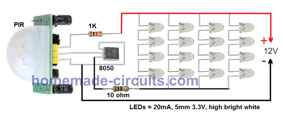
As you can see I have not used any voltage regulator here, since the 1K at the positive works good to limit the current and the voltage to the PIR. This also avoids the base resistor for the transistor.
I have used 16 LEDs, however upto 64 EDs can be used.
For the power supply you can use any cheap 12V 1 amp SMPS
Parts List for the above circuit:
- PIR Module - 1
- 1K 1/4 watt - 1
- Transistor 8050 - 1
- LEDs 5 mA, 20 mA, 3.3V - 16nos, or upto 64 nos
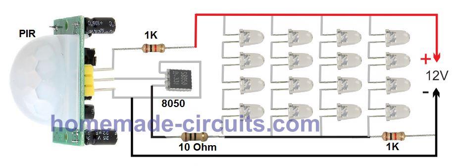
Light Intensity Transition
As requested, the 30% light transition in the absence of a human can be implemented by simply adding a 1K or some other calculated resistor with the negative line of the LED as shown below:
Video Demo
Design# 2
The next two PIR based sensor LED light circuits is similar but has an added feature of detecting the ambient light conditions also. Therefore the circuits will respond based on whether the atmospheric light is sufficiently dark or not and also whether the premise is occupied by a human.
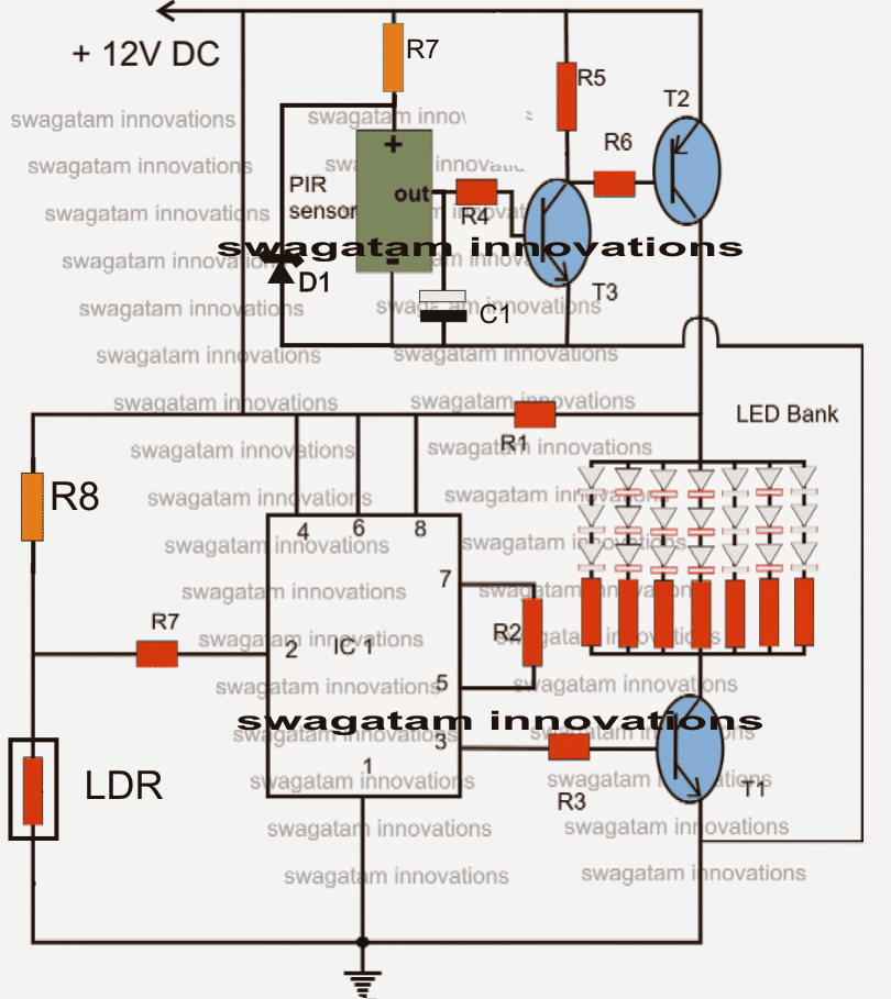
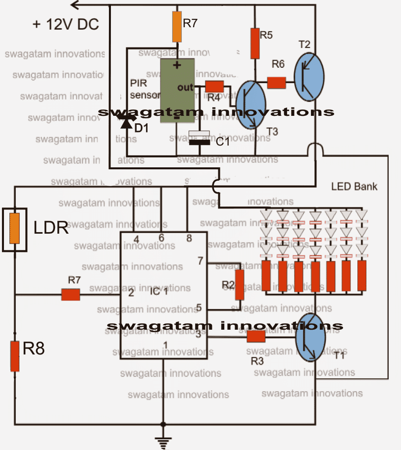
Let's try to understand the PIR based LED lamp circuit functioning from the following points:
The IC 555 is configured as a comparator, the LDR and R8 values are compared for generating an appropriate output.
As long as there's enough light over the LDR, pin#2 of the IC remains high and this keeps the output pin#3 of the IC high as well.
The high output at pin#3 keeps the transistor and the LED switched ON, until the ambient light falls below a predetermined value set by P1.
This means during night or in the absence of light the LEDs too get switched OFF.
The upper section is a proximity sensor circuit. The transistors T2 and T3 are configured as high gain amplifier and is able to sense even minute voltages from the PIR sensor.
In the presence of any human or animal in the specified vicinity, the PIR becomes active and triggers T3, which in turn switches ON T2.
T2 instantly shorts R1, such that the supply voltage reaches the LEDs directly instead of via R1.
This situation brightens up the LED illumination, indicating the presence of a passer by (as stated in the request).
The capacitor C1, ensures the LED brightness stays alive for many seconds, even after the PIR is deactivated.
Parts List
- R1 = 100 Ohms,
- R2,R4 = 100K,
- R3,R5, R6 = 10K,
- R7 (at IC 555 pin2) = 2M2,
- R7 at PIR positive = 10K
- R8 = 2M2,
- C1 = 470uF/25V
- LED resistors = 100 Ohms each,
- T1, T3 = BC547,
- T2 = BC557,
- D1 = 4.7V zener
- LDR = any standard type.
- PIR sensor = any standard type.
- IC1 = 555
Darkness Activated PIR Circuit
The following circuit can be used for automatically detecting human presence, and activating the lights during night time.

Comments (121)
hello sir,
im interested in building the design #2 circuit, but only want the upper portion of the circuit (PIR, two transistors, cap, and resistors) with only the LED bank, i do not need the 555 timer. i have attempted to build twice without success. does design#2 require the 555 timer? why does the “top” portion of the circuit not work when i build it as shown in the schematic? application i want this for is for a closet where the light will go on when the door is opened.
thanks
ge
Hello Geeee,
It can be difficult for me to troubleshoot your circuit, unless I check it practically. However using a 555 is absolutely not required. The LDR function can be added even without IC 555, as indicated in the following article:
https://www.homemade-circuits.com/darkness-activated-pir-lamp-circuit/
In dark activated pir circuit I think first dark or night should be detected and if night then only pir should be activated so that power consumption can be minimised… Just my views..
Thank you, that is a good suggestion…
Thanks.. please enable date and time of post so that viewres can find it easy for responding and can know how older post is.
BTW you are doing very good job of explaining the things in much greater details. Thanks again for your good efforts.
Hi my dear friend, lets say that im using a 10w led for about a 800 lumens light and a 3.7v battery, my cuestion is: What exactly i have to modify in the first desing to make solar using a 10w led and 3.7v instead of 12v. thanks..
Hi, you can use the following set up:
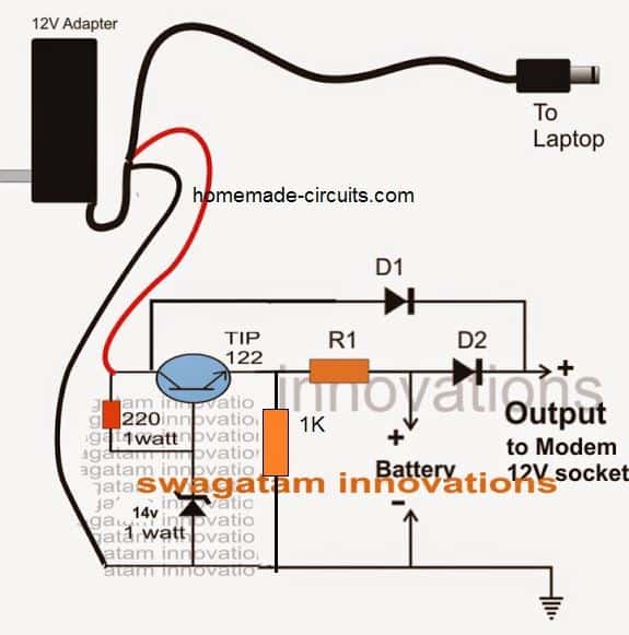
replace the adapter with solar panel, connect the output with the PIR supply input, adjust the zener diode value to get 4.2V across the battery, R1 can be calculated to limit the current to the battery according to its rating.
what size solar panel do you recomend sir?
7V 3 amp should be fine.
MY FRIEND IM TRYNG TO BUILD BUILD A LAMP THAT GIVE ME 1000 TO 1500 LUMENS USING 3.7 OR 12 VOLT. CAN I USE THE SAME SQUEMATIC? OR WHAT MODIFICATIONS , LED TYPE AND COMPONENTS I NEED
My good friend, You can change the 8050 in the first design to TIP122 and connect the desired high watt LEDs. However the 10 ohm resistor will need to be calculated appropriately.
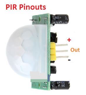
Hi Swagatam, are the emiter, base and collector of the tip122 in the same orientation of the 8050, if not can please tell me the right one? thanks
Hi Julio, I have updated the 8050 pinouts in the above article, for the TIP122 pinout you can quickly Google it and get the details.
got it!!!!!!!! thanks
YOU ARE THE BEST!!!!!!!!
It’s my pleasure!
I HAVE TWO QUESTIONS MY FRIEND: 1) CAN I ADD THE LDR ISDIDE THE PIR SENSOR ?( THIS PARTICULAR PIR HAS CAPABILITY TO ADD AN LDR INSIDE LENS). 2) THE VOLTAGE OF THE LEDS (4 IN SERIE) WILL BE 13.2 VOLTS. WON’T BE A PROBLEM BY USING A 12 VOLTS POWER SUPPLY.
You can add the LDR inside the PIR lens, just make sure it doesn’t block the PIR signals, or doesn’t short anything. 12V can be used for a 3.3V LEDS 4 in series.
thank you my friend. i did it already and work great. good for pir and microwave radar sensor!!!!!
You are welcome!
Utterly stupid design. So many mistakes .
Hi Swag,
I have a LED matrix with 21 LED’s all connected in paralel.
What changes do I need to do in order to connect this matrix to the circuit?
Best Regards.
Nélio Abreu
Hi Neilio,
If they are not power LEDs then you can connect the module directly to any DC source having the same voltage output as specified for the LED module. This voltage should be constant.
However if the module has power LEDs then you may have to employ a current controller also along with a constant voltage, and the LED module will need to be mounted over a suitable heatsink
Hi,
So I don’t have to change the transístor at the LED array in the Darkness Activated PIR Circuit?
The LED’s are all white 5mm standard (not high power) but high bright.
Best Regards,
Nélio Abreu
Hi Nelio,
OK if you want to use it with the last circuit then you must use 5V as the supply and not 12V, because your LEDs are connected in parallel so they are supposed to be rated at 3.3V / 0.42 amps combined. Also for safety put a resistor of 5 ohm 1 watt in series with the module.
For T1 you can use 2N2222 or 8050.
Hi,
Ok. As for the rest of the circuit? The resistors at the 555 IC? Don’t I need to change it?
I presume that R8 controls the sensitivity of the LDR. If so I can replace it with na ajustable resistor, right?
Best Regards.
Nélio
Hi, yes The rest of the circuit can be as is. R8 can be replaced with a 1M pot for achieving the required sensitivity control.
Hi Swagatam,
The PIR sensor described in this circuit is a module or is it a 3 pin device similar to a transístor?
Best Regards.
Nélio Abreu
Hi Neil, it can be either the raw 3 pin sensor or a readymade module, both should work.
The circuit I have used is the following, and it does not respond to anything:
https://flic.kr/p/24J3C2k
Hi again Swag,
I’m still having issues getting the PIRs to work at all. I am trying your second schematic and have built it without the zener as I am using a 5v power supply. The PIR is a RE200B on its own with a 100K resistor connecting the out and – pins. I have built it without the panel of LEDs, only using one.
The trouble is, I have a bag of about 10 RE200B sensors, and they ALL have the same issue, so I think it is not the sensors but how they are connected. Reading with my multimeter from the OUT pin and negative, I am always getting around 0.8v, this barely changes when I move my hand close to the sensor.
Is the PIR in your diagram a RE200B or a ready made unit such as a HC SR501?
Do you have the 100K resistor across the OUT and – pins?
It doesn’t seem to matter what I do, testing the PIRs by connecting any PIR with + connected to the pin closest the metal tab on the unit, the – connected to the pin that is not insulated from the PIR body and the OUT connected to the middle pin, I do not get results.
Am I missing something?
Thanks
Hi Nathan, if you are not getting a varying output from your PIR that simply means the devices may be all faulty. You must first validate the working on your meter, because the transistors in the circuit will respond exactly as your meter responds, so unless the output is verified with a meter you cannot proceed with any circuit integration.
If your PIRs are OK then the meter has to be faulty or may be the testing procedure, the fault will need to be determined before connecting it to any circuit.
The specification of the PIR does not matter all PiRs will behave in the same manner.
I would recommend buying a brand new PIR and get it tested right in the shop itself with a meter, and then bring it home for the remaining procedures
please test by connecting as shown below while testing with meter
I did remove the PIRs from the circuits and tested them for the same result, that was the issue all along. I’m not getting different results either on circuit or off circuit, and the results are not as they are supposed to be…
I have published the datasheet of the device, you can have a look at the details and try to figure out the possible issue and see if you can solve it.
https://www.homemade-circuits.com/pir-sensor-datasheet-pinout-specification-working/
Thanks,
I tested the PIR while it was attached to the HC SR505 and HC SR501 for the results I mentioned above.
So perhaps that is why it is giving incorrect results, you may have to remove and check the sensor separately.
Hi Swag,
I have tried some experiments on HC SR505 and HC SR501 units, measuring the voltage on the RE 200B itself with my multimeter from the source and ground pins. Moving my hand in front caused the modules to trigger and light the LED I had between the GND and OUT pins. However there was little to no change in voltage on the PIR in any case. How is this working on the module, as it reacts with almost no change in the voltage from the PIR itself? This has been the same with those RE 200Bs I have tested on the breadboard, same voltage from the source pin (around 0.5-0.6v).
Also, the delay times in HC SR501 is about 2 seconds minimum. Can I reduce it to 0.5 seconds or less?
Thanks!
Nathan
Hi Nathan, According to one of the datasheets of a similar kind of PIR, the output is supposed to be around 3.5V in response to human presence. Not sure why your sensor is not working without an attached circuit. You can see the datasheet below:
https://www.homemade-circuits.com/wp-content/uploads/2018/04/D204B-PIR.pdf
The delay time can be perhaps adjusted by checking which capacitor inside the module is responsible for this, and then replacing it with a smaller one, however I am not entirely sure about this tweak.
Hello Norman. with transistors the illumination thresholds can never be sharp, you can try a 555 IC instead as shown in the above article, or use another transistor as shown in the following design, this will help reduce the slow glow effect:
https://www.homemade-circuits.com/2011/12/simple-led-automatic-daynight-lamp.html
Hi Swagatam,
I would like to design a PIR activated night light. I am using a PIR sensor, a LDR along with a transistor. I have included a resistor in the output from the PIR to the base of the transistor. The LDR ties the base of the transistor to ground. The size of this resistor increases the amount of darkness before lighting the led. This of course reduces the signal to the base of the transistor which causes the transistor not to fully saturate and the led glows dimly. My problem is I only want the night light to activate when it is totally dark and I want it to provide full power at that point. Right now it starts to glow dimly and gets brighter when the room gets darker. Is there a device like a transistor, FET or other device that will switch to full power completely when receiving a small signal. I don't know how to include a copy of my circuit into this comment. I hope you can follow my reasoning. Thanks!
Can we use this circuit using 6 vol 4.5ah battery supply? Some modification as light illuminating for 11 hour with intensity reduce after 5,hour? Circuit also same function as per your blog.
if possible I'll do it soon…
Sir I can't get it! Can you send any hand drawing?
you can make the second last circuit separately and the 4060 timer circuit with relay separately.
power the 4060 circuit from T2 collector, but the relay coil from direct 12V supply
connect LED assembly through the relay contacts. center pole to T2 collector, N/C…N/O to the LED positives. N/C directly connected while N/O through a resistor.
the value will need to calculated with some trial and error.
That Means as resister value increase intensity decrease? Ok what will be min and max resister value? Any rough drawing where resister will place?
yes that's possible, you can try the second last circuit and integrate a 4060 timer with a relay such that its relay contacts swaps a resistor in series with the LED to reduce the LED intensity after a predetermined delay period
Dear Swagatam,
Thank you for your always fast reply and help.
That did the trick.
You are welcome Henrik!
Hi Swagatam,
To circuit no. 2 (The Simplified version) I have a question regarding remaining the LEDs ON.
I have tried changing the capacitor to bigger ones in order to keep the LEDs on for a longer time period without success.
I have only 1 LED connected to the collector of T2 for test.
When the positive voltage drops from the PIR the LED turns off.
How do I keep the LED on for 30 seconds or more?
Thank you in advance,
Henrik
Hi Henrik, you can do it with the following simple modification:
replace R5 with a high value capacitor, replace R6 with a high value resistor, and possibly replace T2 with a Darlington transistor such as TIP127…that's all this will allow you to get the specified results….by suitably selecting the high value capacitor/resistor values
Hi SM,
I am new to electronics.. i would like to make a PIR based LED light. i have the following PIR sensor, .300ma leds, 1 ohm resistors, 5 V power supply. Please suggest a circuit.
Hi Chandan you can try the second circuit from above article…
use TIP32C for T2 if your LED is rated at 300mA
use 5V as supply and use a 3 ohm 2 watt resistor in series with the LED
Hi Swagatam,
Can I replace R4 with an adjustable resistor so that I can change the time the light stays on after the PIR «shuts» down?
Best Regards.
N.A.
Hi Nelio, yes that's possible, you can do it.
Hi Swagatam,
Can you please explain how the 3rd circuit works? If I want the lights to turn off in 1 min after the person leaves the area, how should I modify the circuit?
Thanks
Hi Anthony, in the third circuit the 555 stage responds and lights up the LEDs in response to the PIR stage output and ambient light conditions(night time)
you can replace the existing 555 with a 555 monostable for achieving the required delays.
hi swagatam,
PIR sensor and amplifier placed a long distance approx 80 ft from LED or buzzer , will signal be send to long distance with low voltage (5-12v) and low current(20mA)?
try putting a 0.22uF capacitor across the receiving input lead of the amplifier and ground.
0.22uf capacitor will be ceramic or electrolytic ?
ceramic…
ceramic 0.22uf with what voltage rating? I have used 440v its working thanks. but what min voltage we should take?
i have taken the sensor wire along with AC wire as there was only one pipe conceled in wall available, now i am getting random signal at the other end. kindly help
Hi playcircuit,
at 80ft it should pose no problems, especially considering the fact that the end gadget would be an amplifier sensitive enough to boost even the minutest of currents that may be achieved
Hi swagatam, I am completely new to electronics and I am going to try and build a version of this circuit using 9 LEDs 3 rows of 3 and have R8 value of 2K. I wish to power the circuit with solar panels. I read your above info regarding using a voltage regulator but can you tell me what one would be used and how it operates please? I have found a 1A positive fixed one but I am not sure what I'd do with it.
Thanks in advance
Jamie
Hi Jamie,
the voltage regulator could be a 7812 IC which is very easy to connect, it has three leads….with the printed side of the IC facing you, the left lead will connect with the solar panel positive, the center lead with solar panel negative and the right side lead will connect with your circuit's positive. The circuit negative can be finally connected with the center lead of the 7812 that is the negative of the panel.
R8 in the 555 stage should be very high, above 200k in order to detect darkness level correctly.
Hello Swagatam,
In the 3rd circuit, what changes do I have to do, in order to replace the LED bank attached to T1 with a relay?
Best Regards.
NC
Hello Nelio, you can directly replace the LED bank connections with the relay coil, make sure to add a freewheeling diode across the relay coil….anode going to the ground lead of the relay coil, cathode to transistor collector side..
Also T2 may be replaced with a BC557 transistor, a 2N2907 will also do
also, the simplified version of the circuit has T2 (bc557) and T3(547) different than the circuit with the 555 timer. is this by design or just a typo?
thanks. keep up the good work!
simply use a voltage regulator stage such as a 7812, or a LM317 in between the circuit and the solar panel for using it safely with any solar panel output.
can you please explain how this can become operational by solar power? thanks
Thanks for pointing that out, yes it is a typo…i'll correct it soon
i have the old circuit (without the zener and a 470uF cap) in operation, should i have any concerns, is it going to burn down my garage? why the changes in the circuit? thanks.
if the PIR is rated at 12V then the zener may not be required otherwise the PIR could get damaged.
the 470uF is for producing a delay-OFF effect, it' not a crucial element in the circuit.
sir i try to make the second circuit i used HC-SR501 PYROELECTRIC INFRARED PIR MOTION SENSOR DETECTOR MODULE if i connect one led to out put pin is working for sen if i connected to the circuit i like to make pir sensor to on/off relay kindly asst me thank you
thank for the replay its working
Satish, you can just remove the LED bank and replace the points with a 12V relay coil.
make sure you have a 1N4007 flyback diode connected in parallel with the relay coil
Hai, I made the third circuit and some problems in that. The circuit is working as "If there is ambient light in the room means, the output at the pin3 of IC1 is low. and if the room is dark means the output at pin3 of IC1 is always high". Means The output at the pin3 should go high when the room is dark and if anyone moves infront of the PIR. But the pin3 of the IC1 is high when the room gets dark itself. The PIR is not working in the circuit itseems. I checked the PIR seperately and its working good. Dont know where is the problem.
And I added a monostable circuit by connecting the pin3 of the IC1 to pin2 of the monostable circuit. Here also a problem. If the pin3 of the IC1 goes low means the monostable circuit IC is getting very hot and fried. Pls give me solution…
OK, fine.
The BC547 connection with the ICs is correct in the shown diagram
The LDR should not become even warm. What have you used for R8?? If R8 is very low, LDR will start getting hot. use 1M for R8
Hai, now the circuit is working good. The problem was with the conections.so when the PIR detects a motion, the output from the pin3 of IC1 is positive high. And thn i made a monostable circuit. The pin2 of the monostable needs negative to activate a relay when pin2 is triggered. so can I connect a BC547 at the pin3 of IC1 by base to pin3 via 10k, emitter to negative and collector to pin2 of monostable circuit?? pls check the diagram imgur.com/USXpBSA
And one doubt, the LDR is slightly getting hot when light is falling on the LDR. Is that normal or connection prob??
If the PIR does not respond T2 will not conduct and the IC555 will not get any supply so how can its pin3 become high in darkness???
Separate the stages completely and check them individually
T2 should conduct only when PIR detects a human presence otherwise not.
Pin2 of the monostable will have a very high resistance so how can the other 555 become hot???
You might have done something wrong in the connections… check it properly or make the design step wise.
Dear Swagatam,
I have an other option of using either 1,2 or 3 string on direct supply without R1 and rest all strings through T2. This will just just keep 1,2 or 3 string when no human is detected and switch on other strings when human is detected.
Dear kkaranjia,
you can try the second circuit, simply add a TIP122 base through 10k resistor with the collector of T3, connect the LEDs across its collector and positive….emitter will connect with the ground.
Dear Mr. Swagatam.
In your 1st circuit diag when the leds are powered via R! they just work at lower voltage but no power is saved as it is consumed by the resistor, so this design can be modified a little to actually save power.
Also i have one question. Just by interchanging the positions of LDR and R8 can this circuit switch on when it is dark n switch off when there is light?
Dear kkaranjia, you can replace R1 with 3nos 1N4007 series diodes for saving energy.
yes interchanging LDR and R8 will reverse the response, please see the last diagram.
Thankyou… I did as u said. Check whether this is correct…
imgur.com/fDespFa
So this will restart the timer of the monostable every time when the PIR detects the motion. Am i correct??
Hai, I made a connection as u said above and tried to restart the timer for the monostable circuit. but its not restarting. pls check it..
yes it's correct.
I am assuming it would work in that way, it will need to be confirmed practically.
After including the monostable circuit to the above and setting the capacitor and resistor for obtaing 50 seconds. Suppose if I walk through the PIR means the monostable circuit start counting for 1-50 seconds. Suppose if I walk thorugh the same PIR at 35th second means will the counting start from 1-50 or not?? If not means how to modify the circuit for restarting timer??
connect pin4 of the monostable to positive via a 10k resistor and also connect this pin with collector of T3 via a 0.22uF resistor.
what should be the minimum and maximum current need for the third circuit??
minimum current should be 150mA, maximum is not important it can be anything.
what is the value for the T1, T2, T3 , C1 for the third circuit diagram?? U mentioned different values in two parts list. And R1 is missing in third circuit. Do I need R7 resistor which is connected with the PIR?? Bcoz i am giving the power supply as 5 v only know. so I am confused. I am giving the power supply as 5v. so do i need to reduce values for all the resistors?? If possible means can u pls tell me the whole parts list for the third circuit diagram??
470uF may be reduced to 10uF/25V or any other lower value, R4 is a must and cannot be removed but 100k is not critical, other values will also work
I added a monostable circuit in the bottom left side.Though I am using monostable circuit, do I need the 470uf capacitor and 100k resistor at the PIR??
D1, R7 can be eliminated for a 5 to 20V PIR device.
yes if a relay is used it may directly connected with pin3 of 555
I got a new PIR sensor. It is mentioned that the operating voltage is 4.5-20v. so If i use this PIR in ur circuit means do I need D1 and R7 at PIR??
And Can I connect the 12v relay directly to the pin3 of IC by removing R3 and T1 ??
Hi, please show me with a diagram so that it becomes clearer to understand.
A 555 monostable will give much accurate and well defined timing response, so it's recommended.
Hai, One doubt. As I want the relay to be in active state for 60 seconds if the PIR detects the motion, U suggested me to include a monostable circuit for that. But U mentioned in the article that "The time for which the LEDs remain ON is determined by the product of R4 and C1". This wil keep the LED bank ON for 51 sec. Instead of LED bank and removing R3,T1, if I connect a relay directly to the pin3 means ,the relay wil be in ON state for 51 sec. So still do I need a monostable circuit??
you may connect the relay directly to pin3 of the monostable
you can do it by connecting the spdt in parallel to the relay contacts which are responsible for switching ON the LEDs
ok. how to manually ON the relay to ON the light?? Is that possible by connecting spdt switch?? Like, switch UP means censor, centre means total OFF, down means manually ON the light. If possible means how to connect?
no R7/D1 won't be required if the supply is regulated to 5V….the same circuit should work for 5V also, no changes would be required.
ok thankyou. Am using power supply as 5v , so is that R7 at PIR is required?? and Do i need to decrease the values of all the resistors and capacitor??
the parts of the last circuit are same as the first one.
R1 is provided for a different application need, please read the circuit description for the first design
Hai, I am modifying the third circuit as follows:-
I am giving input power supply as 5 volt dc , replacing LED bank with 5 volt relay, R8 as 100k preset.
Then if a person pass through the sensor means the relay should be ON state for 60 seconds.Then it should get OFF. what I have to modify for that?
And if there is ambient light means , If I pass thorugh the sensor means the relay should not get ON. The relay should be in OFF state only. what I have to modify for that??
Hi, you will require a monostable circuit using IC 555, R3 and T1 won't be required since you are using a relay.
Connect the monostable pin2 with pin3 of IC1 and connect the relay directly either across pin3/positive or pin3/negative of the monostable.
Set the monostable timing capacitor/resistor for acquiring 60 seconds
Hai, here is the diagram..
imgur.com/rLfrnRh
check wheather the PIR and diode placement is correct. And then can I give a input of 5v instead of 12v?? And I like to replace a 5v relay instead of LED bank. Is that possible?? shall i replace 10k preset instead of R8?? so i can adjust the sensitivity of the LDR.
yes that's fine.
you can use 5V for the entire circuit or only for the PIR while using the 12V for the remaining circuit so that a 12V relay can be used.
replace R8 with a 100k preset.
Hello sir, Could you tell me how to connect another PIR sensor in the circuit?? So if I walk across any one of the PIR means the light should iluminate. And according to the datasheet of PIR sensor, the input voltage for PIR should be 3.3 – 5v DC. But u connected the PIR with 12v. Will it wont fry the PIR module??
Hello, yes you are right it must connected through a 7805 IC, I'll make the changes soon.
connect the two PIR (+) and (-) in parallel and terminate their output pins through individual 1N4148 diodes….anode of the diodes will do to the outputs while the common cathodes of the diodes can be connected to the above circuit (to R4)
Hai, how to connect another PIR sensor in the above circuit??
Bcoz I need a circuit like this :- circuit should contain two PIR sensors and one LDR sensor. The LEDs always should be in OFF state only. If a person cross any one of the PIR sensors means the LEDs should iluminate for 60 seconds and then it should OFF. During day time, if a person cross any one of the PIR sensors means the LEDs should not iluminate. How to control this with LDR??
And how to add a manual switch to the circuit to turn ON the LEDs manually??
Pls help… Am trying to make a circuit for my house staircase..
Hi, you can connect another PIR parallel to the existing one, just put diodes at the output pins of each PIR.
The 555 is placed exactly for the same that is for daytime inactivation of the LEDs, in the second diagram.
for 60 second delay, you will have to incorporate a 555 monostable…i will tell you about it more after you finish the above stages.
sir good day will the simplified version able to power a 12v 15 watts led spotlight?
thanks
Hi aureliano, yes it will.
Hii Swagatam,
I implemented your circuit with LDR & 555 IC, but my LED's are not glowing (Day & night both).
SImple PIR sensor circuit is properly working.
But when i connect IC & LDR circuit as shown above i am not getting high signal at Pin 3.
LDR resistance is around 1.5K in day time & 20K in night time.
Hi Robin,
the value of R8 must be lower than the LDR value at night, only then the LEDs will light up.
you may replace R8 with a 10k preset and set it accordingly.
explain it elaborately and with complete details
"The high output at pin#3 keeps the transistor and the LED switched ON, until the ambient light falls below a predetermined value set by P1."
Where is P1?
Why would anybody just want the LED's to just come on during the day?
I recently changed the diagram, R8 has taken the place of P1 whose value does not need to be varied now.
The circuit is intended to be used in closed rooms during day time when its occupied by people and to be switched off automatically after dark when probably the place is closed.
The circuit just needs to be understood and tweaked as per individual preferences.