The following post discusses the wiring connections for driving a DC motor in clockwise and anticlockwise directions with the help of a single toggle switch and a relay circuit. The idea was requested by one the interested followers of this blog. I have explained more:
Technical Specifications
We have our project in school.
Our professor asks us to design a transistor together with a relay that allows a motor to rotate clockwise and then , a switch will be press , then will rotate counter-clockwise.
In other words a single switch should be able to control the reverse forward rotation of the motor.
Thanks in advance.
The Design
A DC motor can be very simply rotated both ways in clockwise as well as in anticlockwise directions by flipping the supply inputs to it.
However the above reversing requires flipping of both of its wire polarity with the connected supply.
Therefore it cannot be done by using a single relay or switch.
However by using a couple of relays, a single switch operation becomes feasible for toggling the connected DC motor in both reverse and forward directions.
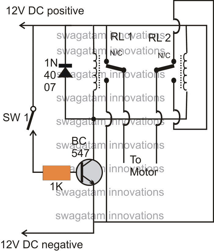
The following circuit shows the wiring details of the relay with the motor which is controlled by a transistor driver stage.
On switching power ON, the motor starts rotating in either clockwise or anticlockwise direction depending upon the wire polarity of the motor.
When SW1 is pressed, the direction gets instantly reversed and continues until S1 is switched OFF.
Actually the transistor stage is not required here, the implementation could be done simply with the relays and SW1.
More simply, the whole reverse forward operation can be conducted using an ordinary single DPDT toggle switch.


Comments
I was benefitted from this article.
Article has been written in lucid manner.
I wish to know how should I open the vertical bar of my Citrus press Juicer having clockwise as well as anti clockwise rotation please?
I am moved to receive your reply
In lucid manner you explained every technical aspect.
I am confident that after your guidance I shall be able to open my citrus juicer
As hobbyist sometimes I try to fix appliances and gadgets at home.
I would love to receive more of such informative articles and videos prepared by you please.
Many Thanks Please
Thanks Radha, I am so glad you liked the post.
I guess most citrus juicers have the vertical cone and shaft mounted on a simple push-fit mechanism. Normally you can remove the cone by pulling it straight upward. In some models the cone may also have a small twist-lock arrangement, so turning it slightly anticlockwise while pulling may release it. If still does not come out then check underneath the cone area because some models use a small screw to secure the shaft to the motor spindle.
Hi Swagatam, I emailed my circuit to hitman. Please review and make changes to correct the circuit. The cd4017’s are sometimes erratic in their advancing. Every revolution should advance the cd4017 and when pin 11 is reached, the up or down relay is switched and the gearmotor should stop. Down or up is selected by another relay on a different PCB. When down is selected, the gearmotor begins rotating clockwise. The slot beam break module sends a pulse to the cd4017 pin 14 for each revolution. When pin 11 is reached, the relay switches and the gearmotor stops. After another event, the up part of the circuit is selected and the gearmotor reverses. The up cd4017 counts the revolutions and when pin 11 is reached, the gearmotor stops.
Hi Norman,
Please try configuring IC 4017 input pins in the following manner and check the response:
https://www.homemade-circuits.com/wp-content/uploads/2025/10/IC-4017-snubber.jpg
Hi Swagatam,
I think I replied to myself. My project is as follows: I am trying to have two tennis balls suspended from a string that will drop down by unwinding the string from a spool attached to the shaft of a gearmotor. The gearmotors are attached to the garage door and are powered by 5vdc through magnetic contacts. The controller is mounted on the garage ceiling and is turned on by a switch that grounds the controller when the garage door opens. My initial design used slot beam break sensors to count the revolutions of the motor using a cd4017. A blade attached to the spool would break the beam and when pin 11 was reached the driving relay would switch and the motor reversed. I had a separate circuit to count the revolutions of the up cycle and when pin 11 was reached the relay switched and the motor stopped. The trouble was the cd4017’s counting was unreliable. Maybe due to electrical spikes. When I tested them on the bench, they worked fine but it was a simple test without everything hooked up. I have limited electronic knowledge. So, I thought I could let the motor unwind and rewind the string (the string is tied to the spool, so if the motor continues, it will rewind the string in the opposite direction) and when the ball got back to the spool shut the motors off with a limit switch. That becomes a problem. Now the next time the garage door is opened, the motors need to reverse and the limit switch has them stopped. I don’t have a problem in reversing the motor but don’t know how to get around the blocked limit switch. There are two units mounted on each side of the garage door to provide a guide to enter the garage in the correct alignment. The tennis balls must be rewound(raised) to prevent them getting under the garage door and to prevent a tripping hazzard.
Thanks Norman,
However, sorry, the mechanism looks difficult for me to understand….I can help you with any related circuits you may want, but getting the mechanical stuff done looks difficult for me.
The 4017 working can be made reliable by putting capacitor snubbers at pin#14, pin#15 etc. and across the supply pins of the IC.
Hi Swagatam,
I am trying to produce a circuit that does the following:
5VDC APPLIED AND MOTOR ROTATES CLOCKWISE UNTIL LIMIT SWITCH IS TRIPPED. 5VDC REMOVED. 5VDC APPLIED AGAIN AND MOTOR ROTATES COUNTERCLOCKWISE UNTIL THE SAME LIMIT SWITCH IS TRIPPED.
I was thinking of using a cd4017 to toggle the circuit when the 5vdc is applied. The first time 5vdc is applied to the circuit the motor would rotate clockwise. The next time 5vdc is applied to the circuit the motor would rotate counterclockwise. I want to use only one limit switch to stop the motor no matter which way the motor is rotating. I have both SPDT and DPDT relays. Is this possible and do you have such a circuit?
Hi Norman,
You can use one limit switch to disconnect the motor during both the rotational direction of the motor, however how to operate the limit switch for the reverse/forward rotations is a mechanical aspect, which you will have to figure out.
When you apply the 5V next time then the 5V polarity must be reversed.
How do you plan to use 4017 for this application?
I’m looking to buy a counter clockwise motor 60 rpm 110volt synchronous motor to turn a polarized disc but it needs to go in the counter clockwise position. What do I ask for and or buy from? Thanks,
Sorry, we don’t sell assembled circuits.
pls guide which relay make use for clockwise and anticlockwise for single phase motor(230V).
its very urgent
sorry, I am not sure how an AC motor may be rotated in both directions.
Hii sir, please help me how i can make automatic rain sensing wiper motor control using 555 timer ic
Hi Kousik, you can refer to the following article
https://www.homemade-circuits.com/2012/09/rain-triggered-instant-start-windshield.html
it's for protecting the transistor from relay coil back EMF
Can you please tell me where to connect those relays … I mean are they directly connected to 12v DC supply…??
yes both the relay coils are connected between +12V and the transistor collector
Sorry, is there anyway to attend a short course for me to learn how to make a device that use both clockwise and unti-clockwise?
The circuit explained above can be used to operate the motor in both clockwise and anti-clockwise directions.
Ooh god you dont need to approve my previous message. I was on the wrong page. I thought I was on the buying page. Sorry for the trouble :p
No problems!
Hello i'm a real noob when it comes to electronics :p Can this motor go counterclockwise to iff I use a DPDT switch? I need a mini motor for a cosplay project so it can spin both clock and counterclockwise.
How to change rotation on my evaporator fan motor 12 volts dc 220ma three wire