An MPPT as we all know refers to maximum power point tracking which is typically associated with solar panels for optimizing their outputs with maximum efficiency. In this post I have explained the 3 best MPPT controller circuits for efficiently harnessing solar power and charging a battery in the most efficient manner.
Where an MPPT is Used
The optimized output from MPPT circuits is primarily used for charging batteries with maximum efficiency from the available sunshine.
New hobbyists normally find the concept to difficult and get confused with the many parameters associated with MPPT, such as the maximum power point, "knee" of the I/V graph etc.
Actually there's nothing so complex about this concept, because a solar panel is nothing but just a form of power supply.
Optimizing this power supply becomes necessary because typically solar panels lack current, but posses excess voltage, this abnormal specs of a solar panel tends to get incompatible with standard loads such as 6V, 12V batteries which carry higher AH rating and lower voltage rating compared to the panel specs, and furthermore the ever-varying sunshine makes the device extremely inconsistent with its V and I parameters.
And that's why we require an intermediate device such as an MPPT which can "understand" these variations and churn out the most desirable output from a connected solar panel.
You might have already studied this simple IC 555 based MPPT circuit which is exclusively researched and designed by me and provides an excellent example of a working MPPT circuit.
Why MPPT
The basic idea behind all MPPTs is to drop or trim down the excess voltage from the panel according to the load specs making sure that the deducted amount of voltage is converted into an equivalent amount of current, thus balancing the I x V magnitude across the input and the output always up to the mark...we cannot expect anything more than this from this useful gadget, do we?
The above automatic tracking and appropriately converting the parameters efficiently is implemented using a PWM tracker stage and a buck converter stage, or sometimes a buck-boost converter stage, although a solitary buck converter gives better results and is simpler to implement.
Design#1: MPPT using PIC16F88 with 3-Level Charging
In this post we study an MPPT circuit which is quite similar to the IC 555 design, the only difference being the use of a microcontroller PIC16F88 and an enhanced 3-level charging circuit.
Step wise Working Details
The basic function of the various stages can be understood with the help of the following description:
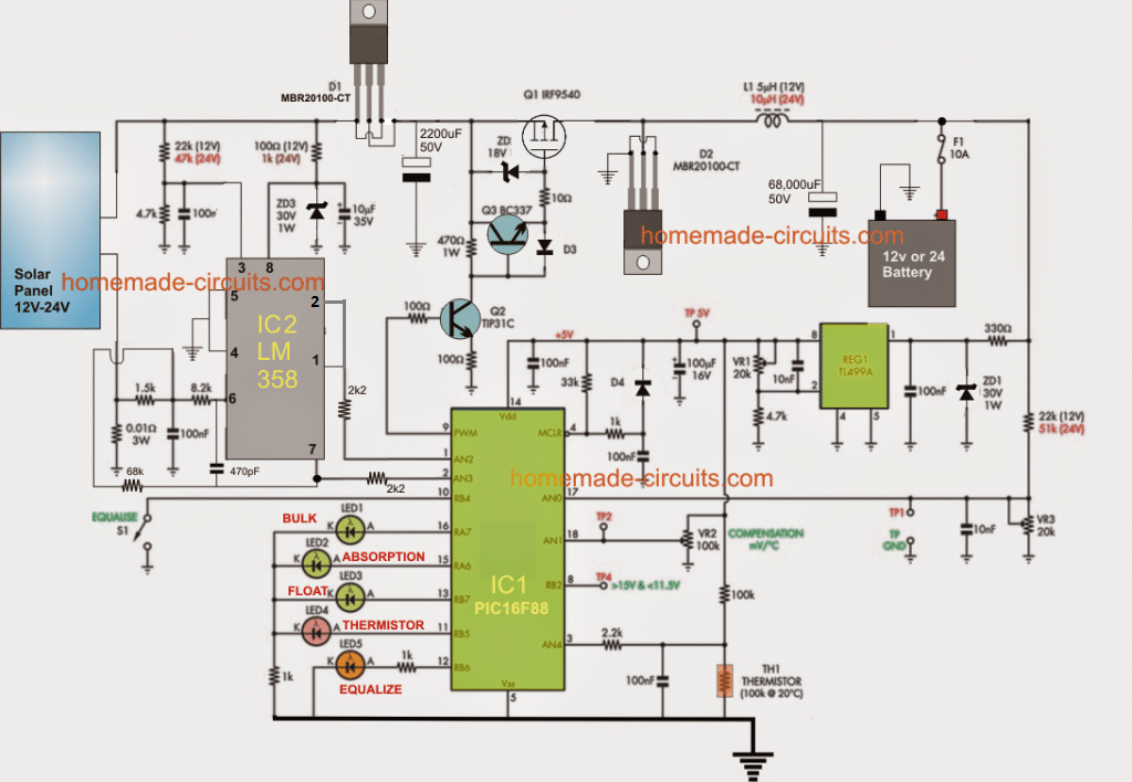
1) The panel output is tracked by extracting a couple of information from it through the associated potential divider networks.
2) One opamp from IC2 is configured as a voltage follower and it tracks the instantaneous voltage output from the panel through a potential divider at its pin3, and feeds the info to the relevant sensing pin of the PIC.
3) The second opamp from IC2 becomes responsible for tracking and monitoring the varying current from the panel and feeds the same to another sensing input of the PIC.
4) These two inputs are processed internally by the MCU for developing a correspondingly tailored PWM for the buck converter stage associated with its pin#9.
5) The PWM out from the PIC is buffered by Q2, Q3 for triggering the switching P-mosfet safely. The associated diode protects the mosfet gate from overvolatges.
6) The mosfet switches in accordance with the switching PWMs and modulates the buck converter stage formed by the inductor L1 and D2.
7) The above procedures produce the most appropriate output from the buck converter which is lower in voltage as per the battery, but rich in current.
8) The output from the buck is constantly tweaked and appropriately adjusted by the IC with reference to the sent info from the two opamps associated with the solar panel.
9) In addition to the above MPPT regulation, the PIC is also programmed to monitor the battery charging through 3 discrete levels, which are normally specified as the bulk mode, absorption mode, an the float mode.
10) The MCU "keeps an eye" on the rising battery voltage and adjusts the buck current accordingly maintaining the correct Ampere levels during the 3 levels of charging procedure. This is done in conjunction with the MPPT control, that's like handling two situations at a time for delivering the most favorable results for the battery.
11) The PIC itself is supplied with a precision regulated voltage at its Vdd pinout through the IC TL499, any other suitable voltage regulator could be replaced here for rendering the same.
12) A thermistor can be also seen in the design this may be optional but can be effectively configured for monitoring the battery temperature and feeding the info to the PIC, which effortlessly processes this third information for tailoring the buck output making sure that the battery temperature never rises above unsafe levels.
13) The LED indicators associated with the PIC indicate the various charging states for the battery which allows the user to get an up-to-date information regarding the charging condition of the battery throughout the day.
14) The proposed MPPT Circuit using PIC16F88 with 3-Level Charging supports 12V battery charging as well as 24V battery charging without any change in the circuit, except the values shown in parenthesis and VR3 setting which needs to be adjusted to allow the output to be 14.4V at the onset for a 12V battery and 29V for a 24V battery.
Programming code can be Downloaded here
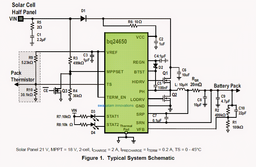
Design#2: Synchronous Switch-Mode MPPT Battery Controller
The second design is based on the device bq24650 which includes an advanced built-in MPPT Synchronous Switch-Mode Battery Charge Controller. It offers a high level of input voltage regulation, which prevents the charging current to the battery each time input voltage drops below a specified amount. Learn More:
Whenever the input is attached with a a solar panel, the supply stabilization loop pulls down the charging amp to ensure that the solar panel is enabled to produce maximum power output.
How the IC BQ24650 Functions
The bq24650 promises to provide a constant-frequency synchronous PWIVI controller with optimal level of accuracy with current and voltage stabilization, charge preconditioning, charge cut-off, and charging level checking.
The chip charges the battery in 3 discrete levels: pre-conditioning, constant current, and constant voltage.
Charging is is cut-off as soon as the amp level nears the 1/10 of the rapid charging rate. The pre-charge timer is set to be at 30 minutes.
The bq2465O without a manual intervention restarts the charging procedure in case the battery voltage reverts below an internally set limit or reaches a minimum quiescent amp sleep mode while the input voltage goes below the battery voltage.
The device is designed to charge a battery from 2.1V to 26V with VFB internally fixed to a 2.1V feedback point. The charging amp spec is preset internally by fixing a well matched sensing resistor.
The bq24650 can be procured with a 16 pin, 3.5 x 3.5 mm^2 thin QFN option.
Circuit Diagram
BATTERY VOLTAGE REGULATION
The bq24650 employs an extremely accurate voltage regulator for the deciding on the charging voltage. The charging voltage is preset by means of a a resistor divider from the battery to ground, with the midpoint hooked up the VFB pin.
The voltage at the VFB pin is clamped to 2.1 V reference. This reference value is used in the following formula for determining the desired level of regulated voltage:
V(batt) = 2.1V x [1 + R2/R1]
where R2 is linked from VFB to the battery and R1 is connected from VFB to GND. Li-Ion, LiFePO4, as well as SMF lead acid batteries are ideally supported battery chemistries.
A majority of over the shelf Li-ion cells can now be effectively charged up to 4.2V/cell. A LiFePO4 battery supports the process of a substantially higher charge and discharge cycles, but the down side is that the the energy density is not too good. The recognized cell voltage is 3.6V.
The charge profile of the two cells Li-Ion and LiFePO4 is preconditioning, constant current, and constant voltage. For an effective charge/discharge life, the end-of-charge voltage limit may possibly be cut down to 4.1V/cell however it‘s energy density could become a lot lower compared to the Li-based chemical specification, lead acid continues to be much preferred battery because of its reduced production expenses as well as rapid discharge cycles.
The common voltage threshold is from 2.3V to 2.45V. After the battery is seen to be completely topped up, a float or trickle charge becomes mandatory in order make up for the self-discharge. The trickle charge threshold is 100mV-200mV below the constant voltage point.
INPUT VOLTAGE REGULATION
A solar panel may have an exclusive level on the V-I or V-P curve, popularly known as the Maximum Power Point (MPP), wherein the complete photovoltaic (PV) system relies with optimum efficiency and generates the required maximum output power.
The constant voltage algorithm is the most easy Maximum Power Point Tracking (MPPT) option available. The bq2465O automatically shuts down the charging amp such that the maximum power point is is enabled for producing maximum efficiency.
Switch ON Condition
The chip bq2465O incorporates a "SLEEP" comparator to identify the means of supply voltage on the VCC pin, because of the fact that VCC may be terminated both from a battery or an external AC/DC adapter unit.
If the VCC voltage is more significant the SRN voltage, and the additional criteria are fulfilled for the charging procedures, the bq2465O subsequently begins making an attempt to charge a connected battery (please see the Enabling and Disabling Charging section).
lf SRN voltage is higher with respect to the VCC, symbolizing that a battery is the source from where the power is being acquired, the bq2465O is enabled for a lower quiescent current ( <15uA) SLEEP mode to prevent amperage leakage from the battery.
lf VCC is below the UVLO limit, the IC is cut-off, after which VREF LDO is switched off.
ENABLE AND DISABLE CHARGING
The following concerned aspects need to be ensured before the charging process of the proposed MPPT Synchronous Switch-Mode Battery Charge Controller Circuit is initialized:
• Charging process is enabled (MPPSET > 175mV)
• The unit is not in Under-Voltage-Lock-Out (UVLO) functionality and VCC is above the VCCLOWV limit
• The IC is not in SLEEP functionality (i.e. VCC > SRN)
• VCC voltage is below the AC over-voltage limit (VCC < VACOV)
• 30ms time lapse is fulfilled after the first power-up
• REGN LDO and VREF LDO voltages are fixed at the specified junctures
• Thermal Shut (TSHUT) is not initialized - TS bad is not identified Any one of the following technical issues may inhibit the proceeding charging of the battery:
• Charging is is deactivated (MPPSET < 75mV)
• Adapter input is disconnected, provoking the IC to get into a VCCLOWV or SLEEP functionality
• Adapter input voltage is below the 100mV above battery mark
• Adapter is rated at higher voltage
• REGN or VREF LDO voltage is not as per the specs
• TSHUT IC warmth limit is identified • TS voltage happens to move out of the specified range which may indicate that the battery temperature is extremely hot or alternatively much cooler
Self-Triggered In-built SOFT-START CHARGER CURRENT
The charger by irself soft-starts the charger power regulation current each time the charger moves into the fast-charge to establish that there is absolutely no overshoot or stressful conditions on the externally connected capacitors or the power converter.
The soft-start is featured with of stepping-up the chaging stabilization amp into eight uniformly executed operational steps next to the prefixed charging current level. All the assigned steps carry on for around 1.6ms, for a specified Up period of 13ms. Not a single external parts are called for enabling the discussed operational function.
CONVERTER OPERATION
The synchronous buck PWM converter employs a predetermined frequency voltage mode with feed-forvvard control strategy.
A version III compensation configuration let's the system to incorporate ceramic capacitors at the output stage of the converter. The compensation input stage is associated internally between the feedback output (FBO) along with an error amplifier input (EAI).
The feedback compensation stage is rigged between the error amplifier input (EAI) and error amplifier output (EAO). The LC output filter stage needs to be determined to enable a resonant frequency of around 12 kHz - 17 kHz for the device, for which the resonant frequency, fo, is formulated as:
fo = 1 / 2 π √LoCo
An integrated saw-tooth ramp is allowed to compare the internal EAO error control input to alter the duty-cycle of the converter.
The ramp amplitude is 7% of the input adapter voltage enabling it to be permanently and completely proportional to the input supply of the adapter voltage.
This cancels away any sort of loop gain alterations on account of a variation in the input voltage and simplifies the loop compensation procedures. The ramp is balanced out by 300mV so that a zero percent duty-cycIe is achieved when the EAO signal is below the ramp.
The EAO signal is likewise qualified to outnumber the saw-tooth ramp signal with a purpose to achieve a 100% duty cycIe PWM demand.
Built in gate drive logic makes it possible accomplishing 99.98% duty-cycle at the same time confirming the N-channel upper device consistently carries as much as necessary voltage to always be 100 % on.
In the event the BTST pin to PH pin voltage reduces below 4.2V for longer than three intervals, in that case the high-side n-channeI power MOSFET is switched off while the low-side n-channe| power MOSFET is triggered to draw the PH node down and charge-up the BTST capacitor.
After that the high-side driver normalizes to 100% duty-cycle procedure until the (BTST-PH) voltage is observed to decline low yet again, on account of outflow current depleting the BTST capacitor below 4.2 V, as well as reset pulse is reissued.
The predetermined frequency oscillator maintains rigid command over the switching frequency under most circumstances of input voltage, battery voltage, charge current, and temperature, simplifying output filter layout and retaining it away from the audible disturbances state.
Design#3: Fast MPPT Charger Circuit
The third best MPPT design in our list explains a simple MPPT charger circuit using the IC bq2031 from TEXAS INSTRUMENTS, which is best suited for charging high Ah lead acid batteries quickly and with a relatively fast rate
Abstract
This practical application article is for the individuals who may be developing an MPPT-based lead acid battery charger with the aid of bq2031 battery charger.
This article includes a structural format for charging a 12-A-hr lead acid battery employing MPPT (maximum power point tracking) for improving charging efficiency for photovoltaic applications.
Introduction
The easiest procedure for charging a battery from a solar panel systems could be to hook up the battery straight to the solar panel, however this may not the most effective technique.
Presume a solar panel bears a rating of 75 W and generates a current of 4.65 A with a voltage of 16 V at normal test environment of 25 ° C temperature and 1000 W/m2 of insolation.
The lead acid battery is rated with a voltage of 12 V; directly hooking up the solar panel to this battery would decrease the panel voltage to 12 V and only 55.8 W (12 V and 4.65 A) could be produced from the panel for charging.
A DC/DC converter may be most suitably needed for economical charging here.
This practical application document explains a model, making use of the bq2031 for effective charging.
I-V Characteristics of Solar Panel
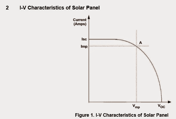
Figure 1 displays the standard aspects of a solar panel systems. Isc is a short-circuit current that streams through the panel in case the solar panel is short circuited.
It happens to be the optimum current that may be extracted from the solar panel.
Voc is the open-circuit voltage at the terminals of the solar panel.
Vmp and Imp are the voltage and current levels where maximum power can be purchased from the solar panel.
While the sunshine decreases the optimum current (Isc) which may be attained, the highest current from the solar panel also suppresses. Figure 2 indicates variation of I-V characteristics with sun light.
The blue curve links the details of the maximum power at various values of insolation
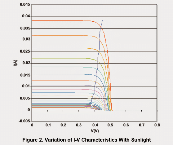
The reason for the MPPT circuit is to try to sustain the working level of the solar panel at the maximum power point in several sunshine conditions.
As observed from Figure 2, the voltage where maximum power is delivered does not alter greatly with sunshine.
The circuit constructed with the bq2031 makes use of this character to put into practice MPPT.
An additional current control loop is included with decrease the charge current as the daylight decreases as well as to sustain solar panel voltage around the maximum power point voltage.
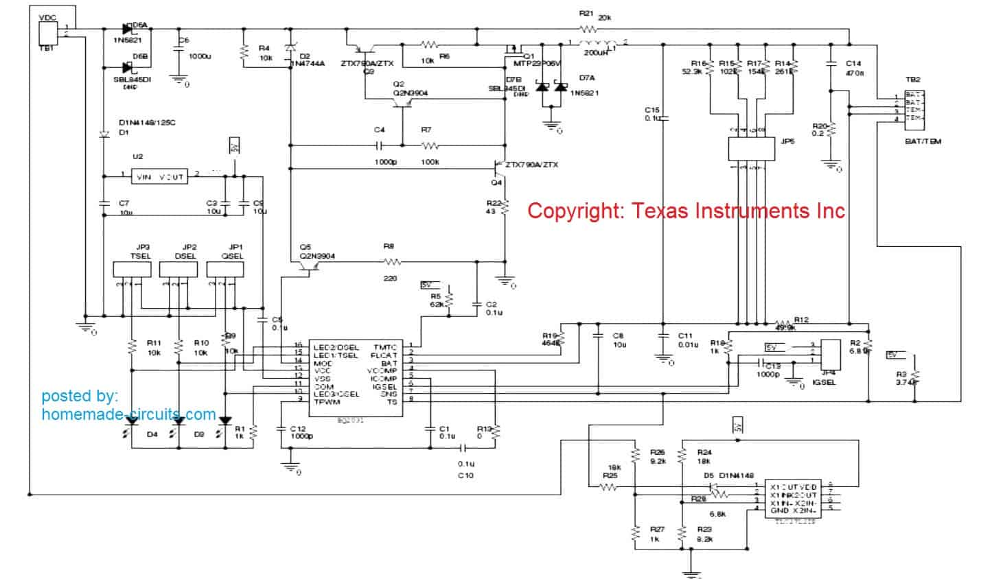
bq2031-Based MPPT Charger
Figure 3 displays the schematic of a DV2031S2 board with an added current control loop added to carry out the MPPT making use of the operational amplifier TLC27L2.
The bq2031 keeps the charging current by retaining a voltage of 250 mV at sense resistance R 20. A reference voltage of 1.565 V is created by using 5 V from U2.
The input voltage is compared with the reference voltage to produce an error voltage that could be implemented at the SNS pin of bq2031 to decrease the charge current.
The voltage (V mp) where maximum power can be acquired from the solar panel is conditioned employing resistors R26 and R27. V mp = 1.565(R 26 +R 27)/R 27.
With R 27 = 1 k Ω and R 26 = 9.2 k Ω, V mp = 16 V is achieved. TLC27L2 is internally adjusted with a bandwidth of 6 kHz at V dd = 5 V. Mainly because the bandwidth of TLC27L2 is significantly below the switching frequency of bq2031, the added current control loop continues to be constant.
The bq2031 in the earlier circuit (Figure 3) offers an optimum current of 1 A.
In case the solar power panel can furnish adequate power to charge the battery at 1 A, the outer control loop does not proceed into action.
However if the insulation reduces and the solar power panel struggles to deliver sufficient energy to charge the battery at 1 A, the outer control loop decreases the charge current to preserve input voltage at V mp.
The outcomes demonstrated in Table 1 confirm the functioning of the circuit. The voltage readings in bold type signify the issue whenever the secondary control loop is minimizing the charge current to preserve input at V mp
References:
MPPT Synchronous Switch-Mode Battery Charge Controller Circuit


Sir, does it mean if you don’t need isolation, one can make mppt without flyback transformer inductor?
That’s correct, you can make a MPPT using a single inductor, if isolation is not needed.
Can these or any of those 3 charge controllers be used for 12v 300w solar panels and 12v 150w battery?
Yes, they can be used, but there’s a much easier option I can provide, here’s the link for it:
https://www.homemade-circuits.com/true-mppt-solar-controller-circuit-using-ic-555/
Thanks for the option provided, but
1. can it work for my 12v solar panel?
2. Can it cut off my inverter if the battery voltage drops low at night, when there Is no sunlight t?
The suggested design will also work for your solar panel and battery. The low battery cut off can be implemented by adding the following explained circuit between the load and the battery:
https://www.homemade-circuits.com/battery-deep-discharge-protection-circuit/
A colleague said he can use lm324 comparator in line with a sg3525 Ic as the pwm signal generator to make a standard mppt controller?
please kindly explain how this can be possible, does it mean he would have 4 fixed standard duty cycle points which the comparator will be changing from one point to another or what, sir?
Dan, It is difficult to describe the circuit unless I see the schematic diagram…
I don’t have it, he just discussed it, that he used sg3525 and lm324, and it was efficient 95%
is possible for a mppt circuit to have high frequency transformer- chopper and inductor in it.
Yes, it is possible and all commercial MPPTs use high frequency ferrite inductor.
Thanks sir.
please what is the meaning and the essence of the pwm tracking, because I understood that the voltage and current vary in the sun intensity. please how does these variations affect the charging efficiency?
from My observation of the commercial mppt, I don’t notice its difference from buck converter.
please how can I extrapolate the first circuit lm358 into a sg3524 buck converter.
Dan, you are correct, MPPT is basically an optimized buck or boost converter, and there’s nothing called PWM tracking in it. Yes, but PWM adjustment is used for adjusting the duty cycle to ensure that the voltage to battery is correctly optimized so that the solar panel is able to provide maximum efficiency using its maximum power point, a voltage level at which the solar panel works most efficiently. So basically we are trying to extract maximum power from the solar panel without causing its voltage to drop due to excessive loading, by optimizing the duty cycle of the buck or the boost converter.
The first circuit is unnecessarily complex, I will try to design an easier concept without a microcontroller soon…
I appreciate your enlightenment, please which one has better efficiency between 555 buck converter and sg3524?
I don’t need adjustable duty cycle, I just need a fixed duty cycle buck converter that can optimise the current at a fixed current.
I need a circuit that can buck convert 150v to 24v at high efficiency.
I am really grateful for your support, thanks.
Dan, Using IC 555 is more compact and efficient compared to using SG3525 IC.
You can take the help of the following articles and build a customized buck converter very easily:
https://www.homemade-circuits.com/calculating-inductor-value-in-smps/
https://www.homemade-circuits.com/buck-converter-calculator/
Sir, between buying a smps adapter for 150v AC to 24vdc and getting a mppt controller which is better? I think mppt has an efficiency of about 96%.
Dan, I think buying the SMPS is better because it will also give you almost the same results in terms of efficiency….assuming the SMPS is of a high quality.
https://www.homemade-circuits.com/convert-smps-into-solar-charger-circuit/
please how will know high quality smps to 24vdc
Also sir, which is more efficient between buck converter and smps?
Buck converter averagely lacks high frequency ferrite transformer but all have normal inductor.
please kindly educate Me for clarity.
I have Ac input voltage that I want to rectify and buck convert to small voltage.
please kindly guide, sir.
Dan, buck converter is also an SMPS without isolation. Buck converters are more efficient if the application is a DC to DC but not good if you want safety and isolation and if you want to use AC mains as the input supply…
please sir, I noticed in the buck converter formula for the inductor value, in mppt, as it is tracking for maximum power from voltage variations, d.c change, so the inductor values should change.
Does it mean that there are multiple inductors for the corresponding voltage variations and d.c?
please kindly explain sir.
Thanks sir.
Dan, We dont use multiple inductors or a changing inductor because in real life we select one fixed inductor, a value that is good enough for the whole range of expected input voltages and current. We choose L in such a way that ripple current ΔI stays acceptable even in worst case.
Let us say:
Vin range = 15V to 22V
Vout = 12V battery
Max output current = 5A
Ripple current target = 10% of 5A = 0.5A
Switching frequency = 100kHz
Now calculate worst case L when Vin is highest (22V), because ripple is highest there:
L = (22V – 12V) * (12/22) / (100kHz * 0.5A)
= 10 * 0.545 / (100000 * 0.5)
= 5.45 / 50000
= 109 uH
So we choose something like 120 uH inductor. This will work fine even if input changes from 15V to 22V.
Good one sir, thanks for this informative guide.
Sir, please for multivoltage mppt, how will the inductor calculated for 12/24v/36v/48v outputs. I appreciate your efforts.
Thanks Dan, you just have to set the maximum duty cycle range to get the corresponding desired maximum output voltage. This range can be set using a rotary switch. To get the relevant max range of the duty cycle and the inductor value, you can take the help of the following calculator. Remember you will also need a feedback system for further tweaking of the output voltage.
https://www.homemade-circuits.com/voltage-to-frequency-converter-circuit/
Sir, with this high frequency ferrite inductor, All mppts use smps topology rather than common buck converter, please am I correct?
Dan, SMPS stands for switch-mode-power-supply, which means using high frequency switching of a ferrite inductor for the conversions… so all buck converters use SMPS topology. A flyback transformer is used only if isolation is required from the input supply.
I want to confirm that all mppt controllers have flyback transformer for isolation and inductor core for filtering noise and harmonics, please I am correct?
It is not compulsory, you can build DC MPPT using a single inductor also….
Sir, does it mean if you don’t need isolation, one can make mppt without flyback transformer?
Dan, yes, that’s 100% correct, please refer to these articles, for example:
https://www.homemade-circuits.com/true-mppt-solar-controller-circuit-using-ic-555/
https://www.homemade-circuits.com/real-mppt-solar-charger-circuit-using-arduino-lcd-and-manual-auto-switch/
I want to confirm that all mppt controllers have flyback transformer for isolation and inductor core for filtering noise and harmonics, am I correct, sir?
It depends on you, how you want to design it…but it is not compulsory for a DC to DC MPPT.
how would i design and construct an mppt charger by switching method
The above circuits also use switching principle…
Hello,
I have a school assignment to design and build an optimizer for a solar panel. It should be controlled by a microcontroller and designed for up to 40V and 15A.
Do you think the first design is suitable? Could you possibly help me with it?
Thank you, App
Hi, The fist design is suitable for your application, but I am not sure about the code, because it looks so lengthy and I have not yet tested it…
You can build a highly optimized solar panel controller simply by using an appropriately rated buck converter.
Have you ever tried building one yourself? Could you possibly share the design you used for your optimizer? I also found other articles published by you, so if there’s another design you believe is best, I’d love to hear about it.
Thanks, App
Sorry, currently I dot not have a microcontroller based design, if it is without a microcontroller then I can suggest…
It would be great to have a recommendation that doesn’t involve a microcontroller, at least as a starting point. Plus, I could learn something from an experienced person.
Sure! You can try the second circuit diagram from the following article, using an iron core transformer. In that case the frequency for the lower TIP122 transistor will be 50 Hz:
https://www.homemade-circuits.com/homemade-solar-mppt-circuit-maximum/
good morning sir…????????????????
can this charger, charge 12v 100 mps or more than
Hi Klin, sorry it won’t charge a 100 amp battery
Well done job Engr. Swagatam.
Plz, if you can help me with the list of components and their specifications, I will be glad… thanks sir in anticipation..
I need help designing a single cell lithium battery charging circuit. It should have the following features
I was looking up various ICs all day, but couldn’t narrow it down. If you could point me a schematic that is already tested that would be a great help.
Please specify the mAh rating and the voltage rating of your cell.
hi Swagatam, this mppt charge control is rated to handle 120w/12 or 220w/24 panel only how I modify it to handle 1500-2500watt panel with 80v
Hi Ike, Sorry, I do not have a 1500-2500watt rated MPPTs at the moment.
Please can you help me with it within a short time.????
Can you please give me 12 v 10 amp mmpt diagram with program for solar street light controller
Sorry, I do not have this circuit with me at this moment
Plz give me a diagram of 12v 60amp mppt charger
I’ve been looking closely at the PIC based controller and think a good addition to this design would be to include a Poly fuse to the Vreg output along with a 5.6v Zener to grnd down line from the 100uf cap. This would be some added protection for the MCU which these are a bit pricey and with the code on it makes it a critical part. It will also protect the rest of the circuit from issues although those components are not so V critical. Including a digital V meter would be nice also to monitor B+ voltage. I’m starting construction on this and will be working to push power up to around 750 watts by adding main diodes and Mosfets, fuses, etc where needed.
I truly appreciate your interest in this project and wish you good luck.
However, I am a bit skeptical about the program code, it looks huge and complex, so please test and verify it before buying all the components.
I have a question for your consideration on the PiC based controller here. That 68kufd cap is a game killer for this project ,Pretty high priced. What I’m wondering is if this much capacitance is truly required? The cost pretty much works out HIGH priced going with multiple lower values no matter what putting a parallel bank together. You have any input on this such as using a lot less like just 10k?
The 68000uF capacitor value is dependent on the battery Ah value. For bigger batteries this capacitor will need to be bigger and vice versa. However, you can experiment with smaller values also and see if that works or not.
Hello again. I’ve been observing a lot of the posts you’ve made now for several years. Now I’ve been looking at this post and specifically design #1. There are still some specifics I want to consider here to make this project suitable for considerably higher power levels, like around ~500 to 800 watts to supply power for an off grid RV system. To speed things up do you have any input I could make use of?
Hi, thanks for exploring this website. The design #1 can be upgraded to the any desired power output by suitably upgrading the Q1, D1, D2 and the inductor wire thickness.
However, I am somehow skeptical about the PIC program code, it looks huge and needs to be checked practically if it really works or not.
Thanks for getting back. I’m currently studying some other posts you did, the de sulphator project. Your’s and another, the 4047 and an NE555 based unit. I’m going to have to put all of this on hold for a month or so till I can place an order for parts to work with these.
Sounds great! no problems, wish you all the best with the projects….let me know if you any further questions.
If a buck boost circuit required so that it can charge at low voltage time?
I have 15 batteries 12V 150Ah connected serially to earn 180V 150Ah to run the UPS elevator.
I need to recharge them from solar by MPPT. What is the best way to connect MPPT that can give me 180V DC to recharge 15 Batteries?
Building an MPPT for a 180V 150 Ah battery can be quite huge and complex, therefore i would recommend you to buy it ready-made instead of making one. The company engineer will explain you how to connect and use it.
Can you send the full Skech of the circuit diagram
And the list of the components
what is reference between pwm & MPPT
what is effencey between pmw & mppt
I’m interested in this article but at the end, it seems to just cut off mid sentence. Can you check and make sure it’s all posted? It seems it got cut off.
The last design is from texas instrument, for the details you can refer to the following datasheet..
https://www.ti.com/lit/an/slva378a/slva378a.pdf
Thank you. I missed that. I enjoy your articles. The way you explain things makes more sense to me. Sometimes data sheets tend to complicate things.
Thanks again.
It’s my pleasure and I am glad you liked the articles.
Tanks sir but where can i apply arduino nano in that circuit diagram
Sure by using arduino nano right?
All Arduino will work actually….
Dear Sir,
I’m seeking for DIY MPPT charger kits.
Can you provide me the contact.
Sorry Raju, I do not have readymade kits for these projects!