This simple homemade mosquito swatter bat neither requires a circuit nor a battery for the operation. The entire design works using a single high voltage capacitor and through quick charging from mains AC socket. (Designed by me)
Introduction
In a few of my earlier posts I have discussed how to make mosquito zappers using the conventional high voltage circuits, and using chargeable battery for generating the high voltages.
Such swatter bats work great but they have some serious drawbacks.
These units use a fairly complex circuit which require a calculated inductor and a switching circuit. The second complex thing in the design is the bat mesh which cannot be hand made and require special equipment and tools for the assembly.
Moreover the battery used with these bats being cheap are prone to faults and finally become useless, or require frequent repairing, which usually become difficult for a layman user.
All these complexities finally compel the user to dump the bat in a scrapyard and go for a new one.
The design explained in this post is quite unique, and is free from all the above downsides, and complexities.
The main features of this battery-less mosquito bat can be understood from the following points:
1) The bat mesh uses a PCB and solderable wire assembly which makes it easier to construct by any user having ordinary technical skills.
2) The bat uses a single high voltage capacitor for charging the mesh, and gets rid of the complex switching circuitry.
3) The high capacitor can be charged directly from the AC mains, and therefore the design does not have to depend on costly NiCd or Li-ion battery, and long charging periods.
You might have by now understood the unique features of this bat, let's move ahead and see how simply this mosquiito bat without battery may be constructed by anybody at home.
How the Bat Mesh is Designed
Referring to the figure below, which looks quite self-explanatory, we can understand the details from the following points:
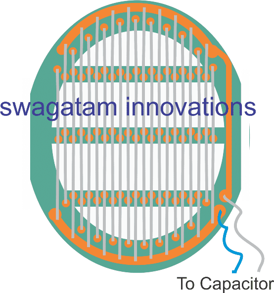
- The green base background is actually a PCB, with copper tracks etched on it, shown in orange.
- The PCB is elliptical in shape with a large central cut out, and a couple of horizontal ribs to enforce better rigidity to the PCB frame.
- The grey lines are tinned copper wires, around 0.5mm in thickness, tightly stretched and soldered end to end across the indicated copper tracks. The wires are alternately arranged and connected with the respective power line tracks, on either side of the layout.
- The wires are also soldered in between across the two central ribs to reinforce them with increased rigidity and firmness.
Designing Swatter Bat without a Battery
That's it, the bat mesh is now ready.
Now I have explained how the stem or the handle of the bat is designed, and the electrical specification details in the following section:
The next image below details the integration of the bat mesh with the handle and the electrical wiring which needs to be done within the internal space of the handle:
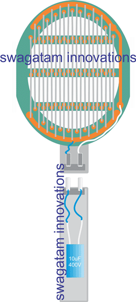
From the images above we can identify the following connection and wiring details:
- The handle upper and lower assemblies preferably needs to be a push-fit type, with corresponding male/female AC pins, such that when the two sections are push-locked, the pins also get plugged in with each other.
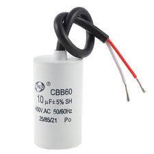
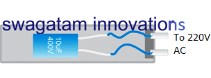
- The lower section of the handle can be seen enclosed with a 10uF/400V capacitor (Non-polar), whose terminals are electrically wired with the external plug pins.
- This section of the handle plays a twin role, first it allows detachment from the bat and plugging into your home mains socket for a 1 second quick charging, and next, the same plug pins are allowed to be inserted back into the upper bat section for arming the bat mesh net.
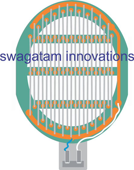
The following figure shows how the lower handle section needs to be detached and plugged to an AC socket for charging the internal 10uF capacitor, (for a 1 second charging).
How the Swatter Bat Works without a Circuit or a Battery
Through the above discussion, you might have already understood the concept, where a high value charged capacitor is used for electrifying the bat mesh and electrocuting the bugs or mosquitoes flying between the parallel wires of the bat net.
That looks pretty simple and doesn't need much of an explanation.
Some Technical Necessities
The proposed design uses a single capacitor for the charging the mesh, which implies that the voltage level is significantly reduced across the net wires, as compared to the conventional bat designs.
Therefore in order to make the design effective, it is important to keep the wires soldered on the bat PCB to be not more than 0.8mm away from each other.
Anything above this distance might allow our tiny friends to dodge away the fence, and to safety.
Warning:
Anything that comes easy invariably possesses some hidden drawbacks and dangers. Here too, although the bat design looks straightforward, the mesh network is held completely exposed to an accidental human touch.
Therefore, once the charged capacitor is hooked-up with the bat mesh, be very cautioned not to allow any of your body part to come in contact with the bat mesh.
Otherwise that could cause a painful memorable jolt to your body. Since the shock is from a capacitor, it won't be lethal, nevertheless it could be quite nasty.