In this post I have explained a simple 20 watt fluorescent ballast circuit using a single chip FAN7711 from Fairchild semiconductor.
The proposed mains 220V operated, 20 watt fluorescent ballast circuit is built around an LCC resonant tank and a half-bridge network.
Implementing Zero Voltage Switching
The main features and operations may be understood with the following explanation:
In order to execute a zero-voltage switching (ZVS) through the half-bridge inverter circuit, the LCC undergoes a high frequency operation beyond the resonant frequency, fixed by the components L, Cs, Cp and RL where RL is the equivalent to the lamps impedance, and it also crucial with the transfer operation of the LCC resonant tank circuit.
The in-built oscillator stage inside the IC FAN7711 is capable of generating optimal driving pulses in order to implement effective lamp ignition and enhance lamp life.
During the procedures, the oscillation frequency goes through the following transitions:
Preheating frequency > Ignition frequency> normal running frequency.
Initially, the lamp impedance is relatively high, but once it’s ignited the impedance is brought down substantially. Due to this high initial impedance, the resonant peak could be very high too, owing to this the lamp is fired at a higher frequency than the resonant frequency.
During the operations, the current fundamentally flows via Cp which becomes responsible for linking up the two filaments of the tube and producing ground path for the passing current.
In the course, the passing current preheats the filament for a quick striking.
The amount of amps that may be required for this is adjustable and could be done by setting up the capacitance of Cp.
Calculating Preheating Frequency
The preheating frequency which forms the driving frequency may be expressed as:
fPRE = 1.6 x fOSC
As soon as the above preheating is concluded, the IC pulls down the frequency, increasing the voltage to the lamp for executing the intended ignition of the lamp.
The ignition frequency which is also the function of CPH voltage may be written as:
fIG = [0.3 x (5 – VCPH) + 1] x fOSC
Where VCPH is the voltage rating of the capacitor used
Once the above operations are implemented, the lamp witnesses a constant frequency drive via an external resistor Rt for the required sustained illumination.
Circuit Diagram
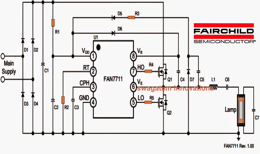
Parts list for the above 20 watt electronic ballast circuit


Comments
The datasheet of FAN7711 says the Power GND and Signal GND must be separated. How can separate them? Can I get PCB document where I can see the Traces, please?
That has to be done on the PCB design layout, please check the PCB layout and do it according to the PCB guidelines.
Thank you so much for the reply. Can I get the link for the L1 inductor? Can I use any 2.5mH inductor? Can you please help me get the inductor link?
You can search for “2.5mH inductor” you will be able to find many online sources from where you can buy it easily.
Dear Swagtam
Can you help me with me a composite ballast circuit for 4 nos 20 W UVC Lamps . Please add a safety circuit . It should light up a LED if any of the 4 20 W UVC lamps is fused .. You may call me at 9971162233 or write at rajivsharma20fbd@gmail.com for any further details . We can work with you on this .
Rajiv Sharma
Dear Rajiv, I have a circuit using iron core transformer, which is easy and cheap to build, will that do?
its ok please suggest that
You can try one of these circuits:
makingcircuits . com/blog/simple-40-watt-fluorescent-tube-emergency-light-circuit/
The indicator t show which lamp has fused can e a little complex, and will need to be designed through op amp circuit.
Thanks for your kind response , just an other question before I test the circuit, in this circuit voltage is not an issue ? Since lamp voltage is 30 v?
Then I think your lamp might not work with this circuit, because it must be rated at 220V to be suitable for this circuit
Hello Sir:
is it possible to use the FAN7711 ic for doing an UV lamp 10 w ballast? or which are your recomendations for uv lamps?
Thanks
Hi Miguel, you can try the circuit, but you may have to modify C6 value to lower the current a bit for the 10 watt lamp.
Can I replace the miller capacitor with electrolytic capacitor
No, that will not do!!
dear sir, i couldn't find this ic, and i don't have coiles , can you give me ballast circuit for 15-20w flourcent, i already have one. But it needs 6.8nf 2kv capacitor, i couldn't find it too
Thanks for the post. What is the main supply used in this circuit? Is it possible to substitute the schematics to the left of the circuit with a 12VDC supply (or other DC value)? I have yet to select my tube – which components would need to be modified for a tube with different specs? Thanks is advance.
…only 20 watt tubes are recommended for the design other wattage may not work correctly
Thanks, the circuit will work with voltages from 120 V to 220 V AC mains supply, it's not designed to work with 12V DC supplies
hi, swagatam can i use 40w tube in this circuit? also i have similar ic called IR2153 could use in this configuration?
Hi SKL, I am afraid 40 watt won't work in the above, rather you could try a 36 watt tube with the following design:
https://www.homemade-circuits.com/2014/04/single-chip-electronic-ballast-circuit.html
Sir can u do for me a high frequency smps inverter for electric fishing used 12 car battery , inverter used in minimum 1.5 metre dept water respectively , shocked by out put connected in two aluminum rodes used a calling bell switch and rodes dipped switch on shocked, sir its the working , can you sent me circuit this id or published here ! arundas118@gmail.com
Arun, I can't publish anything that would kill innocent animals..sorry about that.