In this post I have explained a simple material storage level controller circuit which can be used for automatically activating and deactivating a storage filling motor whenever the storage container is filled to its stipulated threshold level. The idea was requested by Mr Sladjan.
Circuit Objectives and Requirements
- I need help with the engine control filling storage where the material level controlled by photo resistor and a laser beam.
- When the photoresistor see the light it is necessary to start the engine and the fill storage until the level of the material is cut the laser beam and the photoresistor remain without light then turn off the motor and the laser beam.
- After a certain time interval (3 - 5 min) turn on the laser beam and check the level again at the storage material.
- I searched on the site, but I could not find something similar.
The Design
The material storage level indicator circuit as requested above can be built using the following simple configuration:
The functioning of the circuit can be understood as given below:
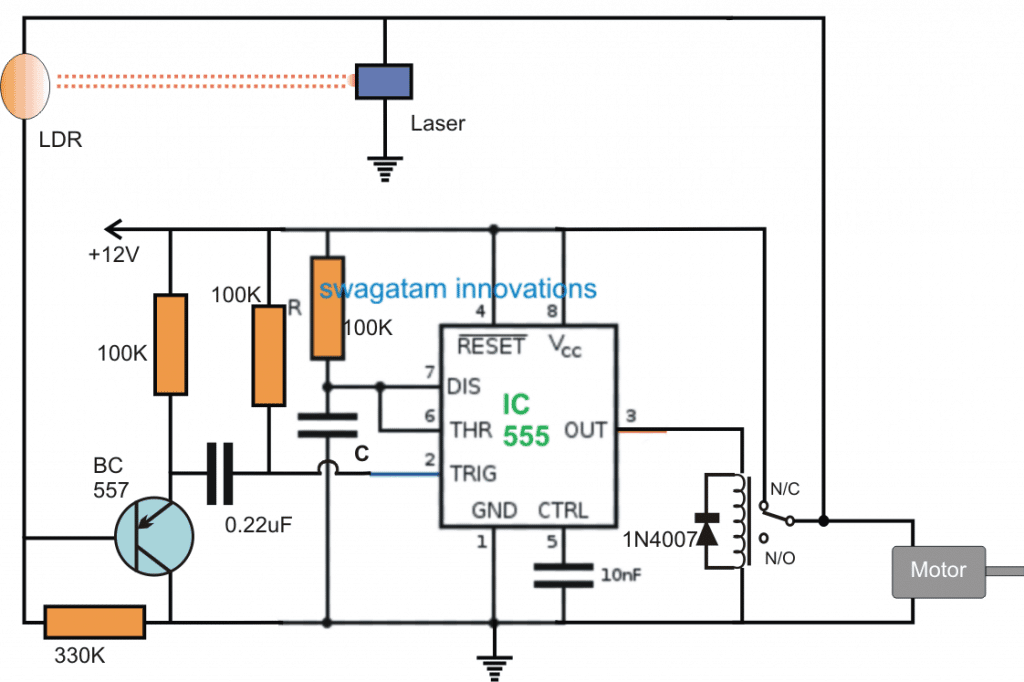
When power is first switched ON, the supply powers the 555 circuit and simultaneously also switches ON the motor, and the laser through the relay N/C contacts causing a low resistance on the receiving LDR device.
The low resistance from the LDR inhibits the BC557 from conducting and the situation locks in this condition, until the space between the Laser/LDR begins filling with the relevant material.
As the material begins filling, at some point of time it reaches the threshold level between the LDR/laser communication beam, and interrupts the beam.
As soon as this happens, the LDR resistance becomes high allowing the BC557 to conduct and trigger the IC 555 stage which is actually wired as a standard monostable multivibrator circuit.
The IC 555 triggers into action and in the course activates the relay. The relay contacts change position from N/C to N/O, which instantly cuts-off power to the laser and LDR network and the motor, as requested by the user.
The situation is sustained until the set time of the monostable lapses and the relay reverts to its earlier N/C position. The circuit now attains its original standby position and activates the motor, until the storage is full again.
The proposed material storage level controller circuit can be further enhanced with an alarm indication by suitably attaching a 12V alarm circuit with the N/O contact of the relay so that whenever the storage is full, the relay disables the laser and also activates the associated alarm.
The value of C can be determined with respect to the 100k resistor from this IC 555 calculator software.


Comments
I am deaf and would like a simple circuit using a 555 to trigger a relay 12v to light a light when the phone rings I know how to wire the ext. speaker jack and the light but i am not Shure how to trigger on the relay with a 555 I am retired and I still have some 555 and relays around There is not a electronic show near me I also have a good supply of the common resistors and caps I can wire the relay so it stays on once to has received a ringtone I want to while in my shop (hobby woodworking) If some one calls or has called I will know,
Also can another 555 be used to amp the audio to run a large 8 ohm external speaker. I worked for many years in electronic but as the years pass I forget more than I ever knew I to was an EE now I am only an old old .
The above article is actually unrelated to your question, but I will still answer it for you. You can refer to the following link, this might help you to solve your problems
https://www.homemade-circuits.com/cell-phone-ring-flashing-lamp-indicator-people-hearing-loss/
good morning sir ,
Can you tell me what components should I use to make this circuit
https://www.homemade-circuits.com/2016/11/ic-4060-timer-latching-problem-solved.html
because of the scheme in the attached photo is less obvious details.
thanks sir.
Wong, please click the diagram to enlarge and you will be able to see all the parts clearly.
all the resistors are 1/4 watt rated.
the transistor is BC557
if you any specific doubt you can feel free to ask
do u have email. i will send you picture of the diode BZX55C.
I try to locate body of the diode and only text BZX55C only sir.
sorry, you will have to do it yourself, you can take the help of the datasheet here
http://www.rectron.com/data_sheets/bzx55c-bs.pdf
or you can experiment with a 3V zener and then other higher values and check which zener allows the machine to start correctly.
sir ,sorry do you know the equality of dioda zener BZX55C ?.. in my old coffee machine there is one dioda zener BZX55C is broken. please help sir. Thanks Sir.
Wong, it's a zener diode, BZX55C is its series number, the actual voltage value should be just beside it, try to locate and identify that number.
thanks for fast respon sir. i will try to make it.
once again THANKS SIR for your help
you are welcome
greating, sir i need help for my coffee machine. i want to make timer switch that i can set it from 0-60sec.
fo exmple :
exp 1 >
1. i set the timer to 50 sec
2. i push start switch ( like bell switch ) the pump will on
3. after 50 second the pump off.
exp 2>
1. i set the timer for 50 sec
2. when i push start switch ,green led on and the pump on
3. and there is another switch that i can use to stop manualy the pump when the timer did't reach 50 sec.
please help sir, thanks a lot sir.
Wong, you can try the concept which is shown below:
https://www.homemade-circuits.com/2016/11/submersible-pumpset-timer-circuit.html
just attach an SPDT switch parallel to the 0.1uF capacitor at the extreme left.
Whenever you switch-OFF this switch the timer starts counting, and any moment you switch-ON the switch, the timer halts and resets.
please make sure to connect a 1N4148 diode from pin#3 to pin#11.
you can also refer to this article
https://www.homemade-circuits.com/2016/11/ic-4060-timer-latching-problem-solved.html
sir swagattam, please do you have a PDF that contained about different sets of circuits diagram. can you send me?
sorry I can't remember which pdf you are referring to?
I'll make immediately to test!
Thanks a lot
but LDR resistance is not supposed to increase slowly, it should increase instantly as soon as power is switched ON and as soon as the laser light falls on the LDR,
secondly, the IC will trigger when there's no laser light on the LDR, as long as laser is focused, the IC output will be OFF.
I think there's some confusion from your part.
Hi Sladjan, IC555 acts like a comparator and also as a timer therefore it is more advantageous than an opamp
I think you can try increasing the 0.22uF to 1uF or 2.2uF and then check the response
Hi Swagatam, I made this circuit, but only works fine with a 10K resistor instead of 330K.
It happens that when the resistance of the LDR increases slowly, do not get trigger on pin 2 of IC555, оnly when LDR resistance jumps sharply.
Can this part of the circuit to be done with a LM741?
sure, thanks! increase 330K to 1M if the laser/LDR fails to disable the BC557