In this post I have explained a simple 21 watt LED lamp circuit module which can be used as a direct replacement for a standard halogen lamp used in motorcycles headlamp.
LED vs Halogen Lamp
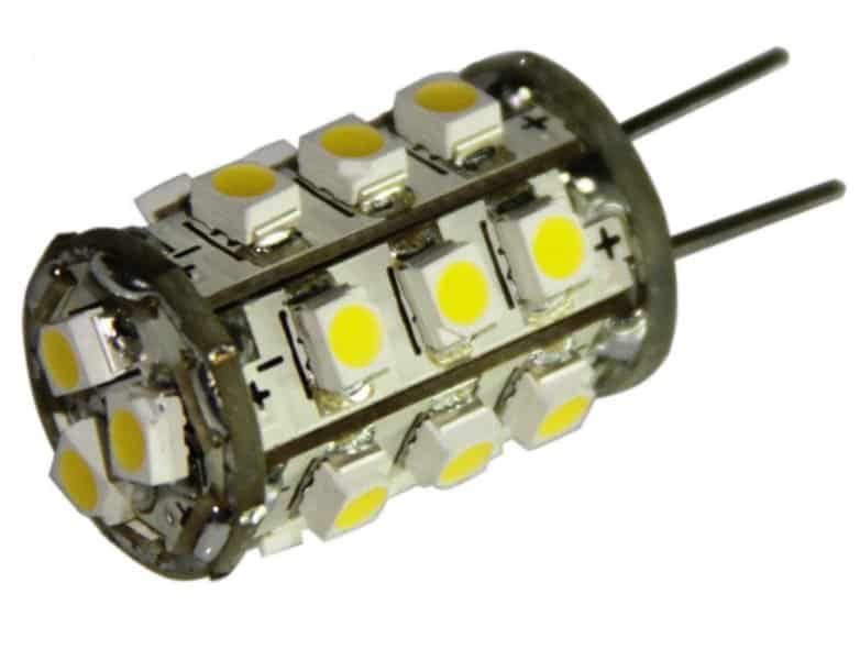
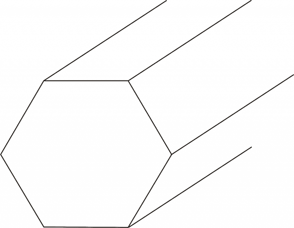
The proposed "halogen" LED lamp replacement module image can be seen below:
Conventional filament type halogen lamp is shown below: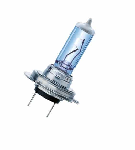
The image at the top shows an example LED lamp replacement for a standard halogen bulb fitting shown below it.
With the easy and extensive availability of LEds, today it's quite possible to make any desired LED lamp module at home for replacing other forms of less efficient lamp options.
So here we'll discuss how to make the proposed halogen LED lamp replacement circuit. I have explained the procedures:
Referring to the above image, we can see the LEDs are wired over 7 separate PCBs and then wired together to form one single module.
How to Assemble the Circuit
Each board can be seen with 3 LEDs each, constituting a total of 21 LEDs.
3nos LEDs are selected because the supply 12V available from the vehicle allows only 3nos to be connected in series, and series connection facilitates sharing the same current across the three LEDs.
Now since more than 3nos. of LEds cannot be accommodated in series, 7 such strings are connected in parallel with each other for achieving the desired 21 watts.
The above assembly must be done over a well designed heatsink cored glass epoxy PCB.
The entire configuration may be tightly fixed over an thick hexagonal aluminum cylindrical former or base to form the proposed halogen LED module unit. The aluminum will hep to sink the generated heat from the LEDs.
A Current Limiter is Essential
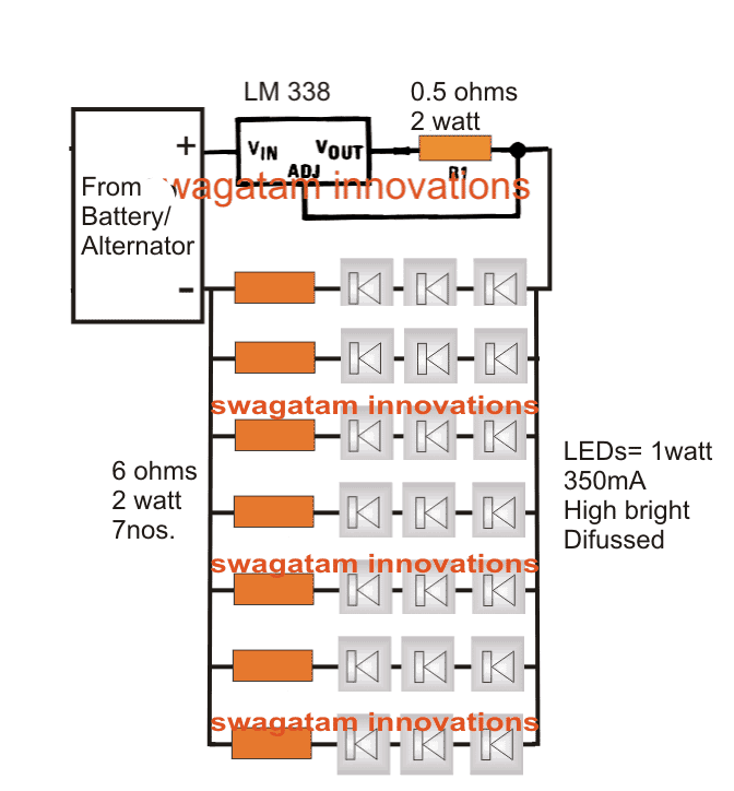
The above unit will strictly require a current controlled driver circuit which can be understood with the following points:
We once again take the help of the versatile LM338 IC for the required current control function.
Referring to the circuit diagram we ca see it in it's simplest current limiting mode. The LEDs consume around 2.5 amps together which is never allowed to exceed by the IC keeping the unit safe from the issue.
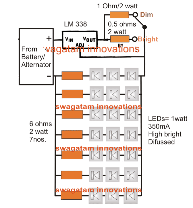
The above design can be upgraded with a Dimming option, as shown below:
Aluminum mount (for heatsink) or base design for fixing the LED PCB assembly
Efficiency Comparison between Motorcycle Halogen Lamp and LED Lamp
<<<<Output----------------Halogen Lamp--------LED Halogen Lamp>>>>
- Nominal wattage----------55 watts-----------------------21 watts
- Nominal voltage-----------12V----------------------------12V
- Test voltage----------------13.2V--------------------------13.2V
- Color temperature -------3200K ------------------------6000K
- Luminous flux-------------1500lm------------------------2500lm


Comments
a fully charged battery will give around 13 v and when the vehicle is running the batt voltage varies from 13 v to 16 v (as most automotive dc regulators are capped at 16 v.) so can we wire up the leds without the limiting resistor and 4nos in series with lm 338 wired to deliver current a bit lesser than the total forward current of the leds?? thanks
Hi all,
Thank you very much for the shared information. I am planning to make a head lamp using the above circuit diagram. I want to make it with a dimmer circuit as shown in circuit no 2. I am fitting it on my Honda Unicorn. Unicorn draws power directly from the alternator. I will be using Philips 1 watt high performance LEDs. I have check the pinout diagram of LM 338 but there is no pin called Adj.
1) What is Adj pin in IC 338?
2) Can I draw power from the alternator or draw power from battery/
3) I have learnt that a LED driver circuit is required to drive a cluster of LEDs. Is it true?
Kindly revert asap,
Thank you.
Ajay
1) check LM338 datasheet, you will get the correct pinout diagram in it.
2) Power can be drawn from the alternator as long as it's connected with the battery also.
3)The above design is a current controlled LED driver circuit.
Hi Swagatam,
Is there any way to make 1 W led driver using 12V DC? I mean atleast powering upto 10-12 LEDs in series, i have gone through your other driver circuits but I would like to power up more than 10-12 at a time, please let me know your thoughts and if possible, the circuit. Thanks in Advance.
Rajthilak K
Hi Rajtilak,
you can try this circuit, the coil will need to be experimented a bit,:
https://www.homemade-circuits.com/2012/09/led-emergency-light-circuit-using-boost.html
For the coil you can try 22SWG wire wound inside a torroid ferrite core with 20 turns.
Hi. Mr Swagatam.
There are 3 pin outs of the Head lamp bulb.
So How its Dimm the head lamp?
Hi Kapila,
The above design does not include a Dimming feature, but it can be easily modified with that feature. It can be done by providing a higher value resistor selection option for reducing current input from the IC, for dimming the LEDs.
I'll try to update it soon.