In this post I have explained a simple 21 watt LED lamp circuit module which can be used as a direct replacement for a standard halogen lamp used in motorcycles headlamp.
LED vs Halogen Lamp
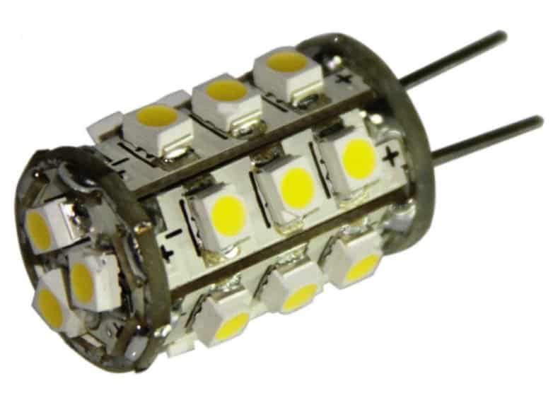
The proposed "halogen" LED lamp replacement module image can be seen below:
Conventional filament type halogen lamp is shown below: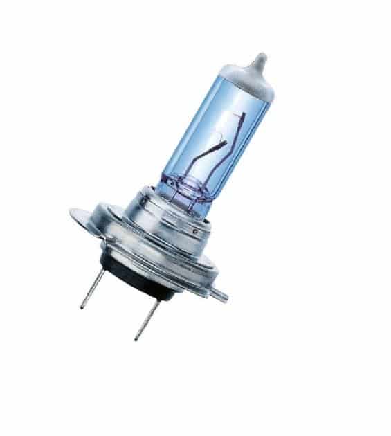
The image at the top shows an example LED lamp replacement for a standard halogen bulb fitting shown below it.
With the easy and extensive availability of LEds, today it's quite possible to make any desired LED lamp module at home for replacing other forms of less efficient lamp options.
So here we'll discuss how to make the proposed halogen LED lamp replacement circuit. I have explained the procedures:
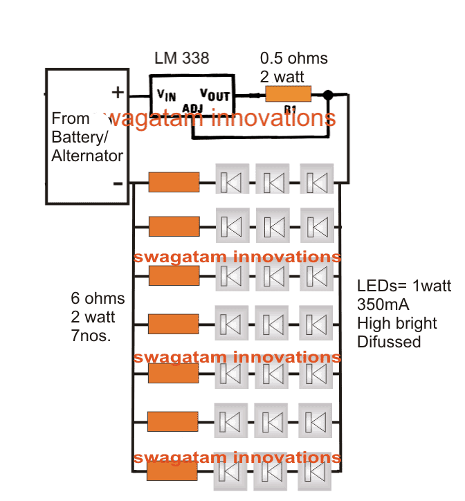
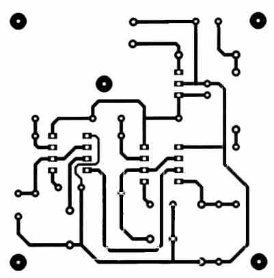
Referring to the above image, we can see the LEDs are wired over 7 separate PCBs and then wired together to form one single module.
How to Assemble the Circuit
Each board can be seen with 3 LEDs each, constituting a total of 21 LEDs.
3nos LEDs are selected because the supply 12V available from the vehicle allows only 3nos to be connected in series, and series connection facilitates sharing the same current across the three LEDs.
Now since more than 3nos. of LEds cannot be accommodated in series, 7 such strings are connected in parallel with each other for achieving the desired 21 watts.
The above assembly must be done over a well designed heatsink cored glass epoxy PCB.
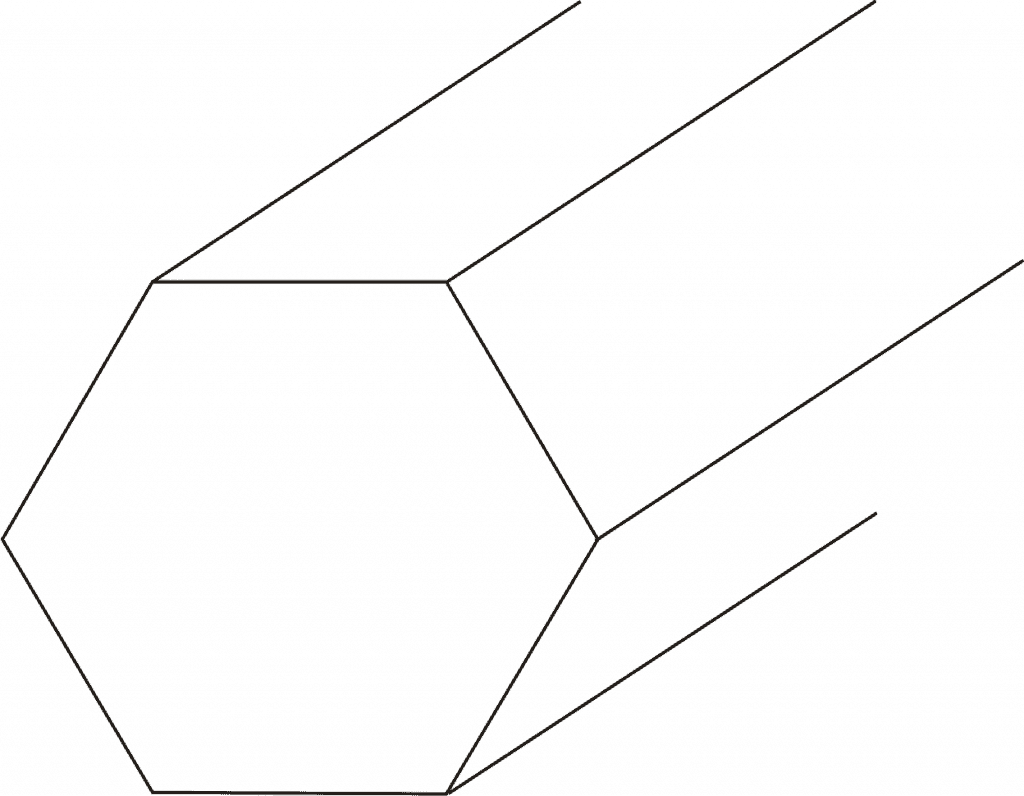
The entire configuration may be tightly fixed over an thick hexagonal aluminum cylindrical former or base to form the proposed halogen LED module unit. The aluminum will hep to sink the generated heat from the LEDs.
A Current Limiter is Essential
The above unit will strictly require a current controlled driver circuit which can be understood with the following points:
We once again take the help of the versatile LM338 IC for the required current control function.
Referring to the circuit diagram we ca see it in it's simplest current limiting mode. The LEDs consume around 2.5 amps together which is never allowed to exceed by the IC keeping the unit safe from the issue.
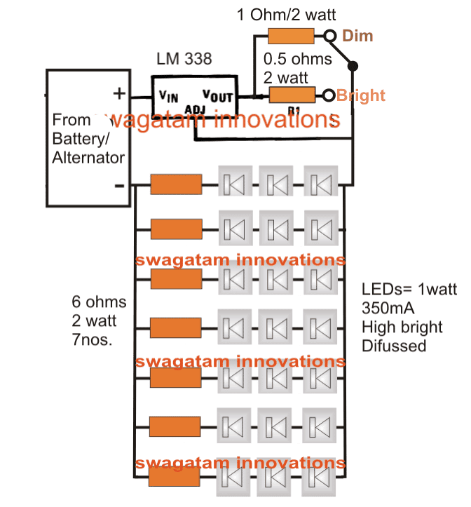
The above design can be upgraded with a Dimming option, as shown below:
Aluminum mount (for heatsink) or base design for fixing the LED PCB assembly
Efficiency Comparison between Motorcycle Halogen Lamp and LED Lamp
<<<<Output----------------Halogen Lamp--------LED Halogen Lamp>>>>
- Nominal wattage----------55 watts-----------------------21 watts
- Nominal voltage-----------12V----------------------------12V
- Test voltage----------------13.2V--------------------------13.2V
- Color temperature -------3200K ------------------------6000K
- Luminous flux-------------1500lm------------------------2500lm


Comments
hi swag
may I ask your advice please ?
I have a 9 volt 10 watt 3 sided led light for my motorcycle. unfortunately this lamp driver was damaged due to overheating. I took apart the casing and saw the electronic parts scattering off the PCB.
The LED light itself is in good condition because I tried it with an external power supply that is connected directly to the COB led and it all lights up.
My question is; can you help make a circuit based on this LM338 for the COB LED driver that I have, complete with the hi-lo LED switch connection
The COB LED data that I got is:
2 x 9V 10 watts @ 900mA / LED for low beam
1 x 9V 10Watt @ 900mA / LED for High beam, in high beam condition 3 LED lights light up simultaneously.
Thank you in advance.
Hi Racky, you can use the following design for the mentioned application:
The values of the resistors are not calculated, you may have to calculate them to set the precise current limiting ranges
Here’s a more correct design which will allow all the LEDs to light up together in the high bright mode:
Hello, I have five 5w LEDs I'd like to use together. Each one has a voltage drop rating from 6-7 and forward current of 700ma. Can you help me decide which resistors I need? I'd like to use the dime option too.
You are welcome….If dimming option is required then you could opt for the second circuit, and use a 1 ohm 5 watt for the other resistor associated with the dimmer switch.
Thank you so much for your help! What if i wanted a dim switch? What would you recommend?
OK great, in that case you can try the first circuit from the above article, use one LED on each string, so you will 5 strings for the 5 LEDs.
use 8 ohms 5 watt resistor in series with each of the LEDs, and use 0.35 ohms 5 watt resistor for the LM338 output resistor
I'll be making a device as the above but on a heat sink with a small fan. It's a regular 12v motorcycle battery so it'll range anywhere from 12-14 volts. Thank you 🙂
Hi, where do you want install them, or what supply voltage do you have for these LEDs
ic LM338 hard to get so i want replace it with LM317,with LM338 we can wire 7nos and the question is how much nos of the leds when i use LM317?i need your help.thanks in advance.
3 strings can be used, with 3nos 1 watt LEDs on each string and the LM317 mounted on a huge heatsink
im wondering if there is a replacement part LM338, LM338 is difficult to get in where I live, more than 20 electronics store I was looking but they do not have. is there any substitute LM338 IC, and IC series what to replace, thanks in advance (sorry bad english,im using google translate)
sorry there's no direct replacement for this IC, alternatively you can try the following discrete method of replicating this IC
https://www.homemade-circuits.com/2012/01/how-to-make-versatile-variable-voltage.html
helo, i want to replace, bike 35w halogen bulb to 20w LED..What diode do i need to use, to make the bridge rectifier nd also the capacitor value for the same. thanks
hello, you can use 6A4 diodes for the bridge, and a 6800uF/35V caapcitor
Hello sir,
I am trying to bi-color LED (Warm and Glow) to change the color from warm to glow by using the dimmer circuit. That's different than changing the brightness by the dimmer.
I gave an idea to do that but I need help here. My idea when you use the regular dimmer the warm LEDs will start light up until it get full brightness and the glow lEDs will be at full brightness and as you use the dimmer it will bright down until get OFF. Do you have any idea how i can achieve that.
Thanks in advance,
Hello David,
In simple words you want a dimmer circuit that can implement a smooth transition of the LED illumination from warm white to cool white and vice versa through the control of the dimmer circuit…. right?
Sir thank u for reply, Sir can u please tell me the value of capacitors and bridge rectifier and after this what component used?
0.45amps looks quite small for the headlights, it should be at least 2 amps, you can use 1N5408 diodes for the bridge rectifier and for the capacitors you can try 4 nos of 6800uF/25V in parallel,
Sir any alternate of super capacitor? And i think led current is about 0.45 amp
Syed, please specify the LED wattage, that will help me to figure out the bridge rating and also the capacitor value roughly….please remember that super capacitors are very costly…but are almost permanent
Sir meri ap se request hay k ap aisi led headlight circuit design karain motorcycle k liye jis ki roshni bohot tezz ho or wo without battery pe chalain bike ki power pe mere matlab hay k meri bike me abhi battery nahi hay laikin jb bike start hoti hay tu light on ho jati hay laikin wo shayad ac source hay or wo acceleration pe depend hay zyada acceleration ho gi tu zyada tezz light chalti hay please aisa kuch design karain
Syed, you can try using a bank of super-capacitors with the supply after rectification using a bridge rectifier, this will probably help the LEDs to produce a constant glow regardless of the motorcycle speed.
Hello sir,
I need your help i made a bike led bulb
I installed 2 led of 20 waat and 3 led of 12 waat
Please help me to design it's circuit because when we connect direct to battery it will turned on it will heat and fused after some time so give me correct circuit diagram please help me
Hello Abhishek, any high watt LED will get burnt if proper heatsink and current regulator are not used with it.
You will need to mount them on large heatsinks and inset the following explained current regulator between the supply and the LEDs:
https://www.homemade-circuits.com/2013/06/universal-high-watt-led-current-limiter.html
Swagatam you have shown 21 leds which are producing lumen between 1500-2500 lumen…if we calculate lumen per led it makes atleast 71 lumens for a single led….could you plz guide where to procure such high lumen led's and what is estimated price for them…..
Thanks
sir which led have to be use i mean led number, or can i use smd led 5730 with your resistor value. wating for your reply sir
Sameer, the circuit shows a set up for SMD 1 watt LEDs, for other LEDs you'll need to calculate the resistors accordingly
please read the following article for more info regarding the subject:
https://www.homemade-circuits.com/2013/06/universal-high-watt-led-current-limiter.html
While connecting the LEDs in series it is important to see cathode and anode terminal, my question is that sequence of terminals really matters.?? Can I connect the LEDs in series in any manner without seeing the positive negative terminal?
yes for LEDs must be always connected by observing correct polarity especially when connected in series, even if a single LED is connected in reverse the whole array will remain shut off or may get damaged.
Ok i will try thanks
So we cannot make AC led Series bulbs
you'll have to include the high voltage isolating capacitor, rest of the components can be eliminated.
make two 50 LED series and connect their opposite ends together, meaning the anode end of one series should be connected with the cathode end of the other series in both the ends.
now simply connect one end of this assembly to one of the mains terminals while the other to the other mains terminal through a high voltage capacitor.
the whole set up will be too dangerous to touch, exercise adequate caution.
Thanks for ur prompt reply bt sir can we run the LEDs without the circuit by adding some ics to each led………. I want to run it direct on 230v AC without any circuit like festival series lamps
LEDs are different from filament bulbs, without capacitor the LEDs will start blowing off with slightest voltage fluctuations if connected directly or through resistors. therefore the recommended capacitive circuit has to be used with it.
Sir actually I want to make 100 nos of led toran of 2 array each array of 50 leds I am trying to convert leds in AC bulbs like 6.2 v festival decoration lamps so that's my question sir
You can use the following circuit, and simply connect the two arrays in parallel across the outputs:
https://www.homemade-circuits.com/2012/04/how-to-make-led-bulb-circuit.html
Hello sir i am trying to make AC 1 watt bulb like 6.2 v 3 amp miniature lamp ……so it will be easy to solder led in series without seeing plus and minus of led so pls help ………..Thanks in Advance
hello basit, I did not quite understand, where and how do you intend to solder the LEDs??
Hello sir i am trying to make AC 1 watt led bulb like 6.2 v 3 amp miniature lamp or festival decoration lamp so it will be easy to solder led without seeing plus and minus of leds so pls rpls ……and Thanks in advance
thanks for the suggestion and for the prompt response; thanks once again !!!!
i have a 20v 3amp DC out; can i use 50ohm 2watt resistor in series for a single LED 3watt
R = 20 – 3.3/0.9 = 18.55 ohm
W = (20 – 3.3) x 0.9 = 15 watt
please refer to the above specs…you'll need around 20 ohm, 15 watt resistor for the said implementation
Can this be use for high and low light control in normal car headlight
yes it could used but the light would be relatively insufficient for a car headlight application
then could we wire 4 white leds per string in series with a 47 ohm resistor (for 8mm led 20 ma current, taking 14.5v batt voltage) looking for making led tail light. thanks.
if it satisfies the calculations then yes it can be done.
Hi Mick,
I think a simple buck converter should be enough to ensure your headlamp lights up much brighter under all conditions.
You can try the the following circuit for fulfilling the above requirement:
https://www.ti.com/lit/ds/symlink/lm2596.pdf
These modules are also available readymade from the market.
The LED can be a 3V-3.7V Round COB LED Light Double Ring Cool White LED
Please let me know if you have any further doubts or questions…
Hi Swagatan
I have a small 1970 125 6v ac Magneto system Motorbike.
The Lights are awful
I want to use LED bulbs.
The AC Power out put from the single coil magneto only just powers a 20 watt head light bulb. A single diode from a coil tap also charges a small 6v battery which then powers just 21w brake light and 10w indicators. The main Head light is powered direct ac from the mag
Supplied power from the magneto coil is low and varies with revs
So as not to waste power. Shunt or series regs turn pwr int heat.
I can not get a SEPIC or BUCK regulator to work down further that 4v
At tick over revs the the bulb will go out.
Any Ideas There must be some circuits out there.
for a single string it will do but when more parallel strings are involved individual resistors become necessary for uniform distribution of current through the strings.