• Skip to main content
  • Skip to primary sidebar

Homemade Circuit Projects

Need circuit help? Post them in the comments! I've answered over 50,000!

Blog | Categories | About | Contact | Calculators-online
You are here: Home / Sensors and Detectors / Make this Temperature Indicator Circuit with Sequential LED Display

Make this Temperature Indicator Circuit with Sequential LED Display

Last Updated on December 31, 2018 by Swagatam 2 Comments

In some of my earlier articles we have seen a few simple and interesting temperature indicator circuits, in this article we will try to upgrade one of them into a sequential form.

All these circuits are useful in some or the other ways, however these are not equipped with  step wise temperature level indicator arrangement and therefore tracking the varying levels of temperature cannot be identified using them.

The present design eliminates the above issue, as here the entire temperature range becomes visible through an arrangement of an LED array.

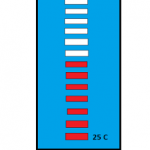
20 LED Sequential Temperature Readout

The LEDs in this circuit reads the temperature levels discretely via 20 steps of LED indications.
The proposed sequential LED temperature indicator circuit is definitely the simplest to build, since it is based on a single outstanding IC LM3914 from TEXAS INSTRUMENTS, which single handedly performs the whole action of displaying the readings in a sequential manner.

The LEDs show an incrementing temperature through a single illuminated LED at the relevant positions of the array, thus the present design shows a dot mode indication instead of a bar graph.

The dot mode arrangement specifically helps to save battery power because only one LED is involved for the required indication at any instant.The IC LM3914 is basically a millivolt measuring device which is able to convert a varying milli volt input into a corresponding LED readout at its output pin outs.

Here the input is derived from another interesting IC LM35 from TEXAS INSTRUMENTS, which is configured as an ambient temperature sensor device.

LM35 for Temperature Sensing

The IC LM35 coverts the temperature differences around it, directly into varying milli volts across its output.

For every single degree change in the temperature, the IC LM35 generates an output with a 10 mV variation.

This correspondingly varying milli volts is applied at the input of the IC LM3914, which readily accepts these variations, making them visible at the output through the connected LEDs.

Thus as the temperature around the IC LM35 increases, it generates a correspondingly increasing mV  across its outputs which is in turn transformed by the IC LM3914 into an LED readout, displaying the relevant level of the sensed temperature.

The LED array should be appropriately calibrated, through some trial and error and some practical experimentation.


temperatureindicatorcircuitwithLEDdisplay


You'll also like:

  • 1.  Shock Vibration Detector Circuit using 801S Sensor
  • 2.  Make this Simple Weather Station Project for Homes and Offices
  • 3.  ACS712 Current Sensor Circuit Diagrams and Datasheet
  • 4.  Digital Up/Down Volume Control Circuit
  • 5.  Make this EMF Pump Circuit and Go Ghost Hunting
  • 6.  Interfacing DHTxx Temperature Humidity Sensor with Arduino

About Swagatam

I am an electronics engineer with over 15 years of hands-on experience. I am passionate about inventing, designing electronic circuits and PCBs, and helping hobbyists bring their projects to life. That is why I founded homemade-circuits.com, a website where I share innovative circuit ideas and tutorials. Have a circuit related question? Leave a comment.... I guarantee a reply!

Previous Post: « 4 Universal Electronic Thermometer Circuits
Next Post: 1A Step-Down Voltage Regulator Circuit – Switched Mode 78XX Alternative »

Reader Interactions

Comments

  1. Fabricio Martinez says

    September 29, 2024 at 8:53 pm

    How are you!!! I would like to implement that circuit to the vehicle’s engine to monitor its temperature since it is manufactured, my car does not bring it, it is a 2002 Ford Ka.

    Reply
    • Swagatam says

      September 30, 2024 at 8:10 am

      I am good, thanks…Sure, you can use the above circuit for monitoring your car engine heat…let me know if you face any problems with the circuit.

      Reply

Need Help? Please Leave a Comment! We value your input—Kindly keep it relevant to the above topic! Cancel reply

Your email address will not be published. Required fields are marked *

Primary Sidebar

Subscribe to New Circuit Ideas

Categories

  • Arduino Projects (87)
  • Audio and Amplifier Projects (132)
  • Automation Projects (17)
  • Automobile Electronics (101)
  • Battery Charger Circuits (82)
  • Datasheets and Components (103)
  • Electronics Theory (143)
  • Free Energy (37)
  • Games and Sports Projects (11)
  • Grid and 3-Phase (19)
  • Health related Projects (25)
  • Home Electrical Circuits (12)
  • Indicator Circuits (14)
  • Inverter Circuits (87)
  • Lamps and Lights (142)
  • Meters and Testers (69)
  • Mini Projects (46)
  • Motor Controller (64)
  • Oscillator Circuits (27)
  • Pets and Pests (15)
  • Power Supply Circuits (108)
  • Remote Control Circuits (50)
  • Security and Alarm (64)
  • Sensors and Detectors (101)
  • Solar Controller Circuits (59)
  • Temperature Controllers (42)
  • Timer and Delay Relay (49)
  • Transmitter Circuits (29)
  • Voltage Control and Protection (37)
  • Water Controller (36)

Calculators

  • Battery Back up Time Calculator
  • Capacitance Reactance Calculator
  • IC 555 Astable Calculator
  • IC 555 Monostable Calculator
  • Inductance Calculator
  • LC Resonance Calculator
  • LM317, LM338, LM396 Calculator
  • Ohm’s Law Calculator
  • Phase Angle Phase Shift Calculator
  • Power Factor (PF) Calculator
  • Reactance Calculator
  • Transistor Astable Calculator
  • Transistor base Resistor Calculator
  • Voltage Divider Calculator
  • Wire Current Calculator
  • Zener Diode Calculator
  • Filter Capacitor Calculator
  • Buck Converter Calculator
  • Boost Converter Calculator
  • Solar Panel, Inverter, Battery Calculator
  • Wire Current Calculator
  • SMPS Transformer Calculator
  • IC SG3525, SG3524 Calculator
  • Inverter LC Filter Calculator

People Also Search

555 Circuits | 741 Circuits | LM324 Circuits | LM338 Circuits | 4017 Circuits | Ultrasonic Projects | SMPS Projects | Christmas Projects | MOSFETs | Radio Circuits | Laser Circuits | PIR Projects |

Recent Comments

  • Swagatam on Best Electronic Circuit Projects
  • TOMMY on Best Electronic Circuit Projects
  • Swagatam on Inverter Circuit with Feedback Control
  • Jerry Adeosun on Inverter Circuit with Feedback Control
  • Swagatam on Contact

Company

  • Privacy Policy
  • Cookie Policy
  • About Me
  • Contact
  • Disclaimer
  • Copyright
  • Videos
  • Sitemap

Social Profiles

  • Twitter
  • YouTube
  • Instagram
  • Pinterest
  • My Facebook-Page
  • Quora
  • Stack Exchange
  • Linkedin
  • © 2025 · Swagatam Innovations