• Skip to main content
  • Skip to primary sidebar

Homemade Circuit Projects

Need circuit help? Post them in the comments! I've answered over 50,000!

Blog | Categories | About | Contact | Calculators-online
You are here: Home / Sensors and Detectors / Single IC Piezo Driver Circuit – LED Warning Indicator


Single IC Piezo Driver Circuit – LED Warning Indicator

Last Updated on December 31, 2018 by Swagatam Leave a Comment

The single IC piezo driver with LED explained here can be used as a warning indicator device in conjunction with some sensor for generating an audible as well as a visual indication.

Table of Contents
  • How the Circuit Functions

How the Circuit Functions

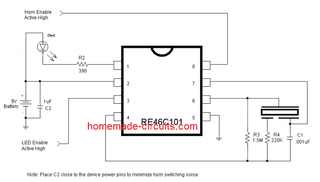
  1. The circuit of this piezo cum LED driver, warning indicator circuit utilizes just a single chip RE46C101 from microchip, for implementing all the procedures.
  2. The chip has the feature of a built in piezo driver as well as a LED indicator circuit.
    The chip is operated using a single 9 volt PP3 cell, which is applied across its pins 2 and 5.
  3. The piezo driver output must be terminated to a three pin type piezo transducer and connected correctly as shown in the figure.
  4. The outer metal case of the piezo goes to the pin #6, the inner white portion which covers maximum surface goes to pin#7while the smallest section of the piezo at the center goes to pin#4 via R4.
  5. The IC will deliver a sharp, chilling frequency over the piezo producing an ear piercing warning sound.
  6. The audio is accompanied with a simultaneous LeD indication at pin #1 of the IC.
  7. The above execution takes place when a high logic supply is applied at pin #8 of the IC.
  8. This logic input may be derived from a sensor configuration for triggering this circuit.
  9. For example, this single IC piezo driver circuit may be used in conjunction with a smoke detector sensor, when a smoke or fire is detected by the sensor, it sends a high logic to pin #8 of the IC for enabling the required warning alert indications from the IC outputs.
warning message: electricity is dangerous, proceed with caution
single IC piezo driver circuit


Courtesy - ww1.microchip.com/downloads/en/DeviceDoc/22163A.pdf
You'll also like:

  • 1.  How to Make LED/LDR Opto Coupler
  • 2.  How to Make a Transformer Winding Counter Circuit
  • 3.  Motion Detector Circuit using Doppler Effect
  • 4.  Vibration Meter Circuit for Detecting Vibration Strength
  • 5.  Simple Vibration Sensor Circuit
  • 6.  Very Low Frequency (VLF) Detector Circuit

Filed Under: Sensors and Detectors Tagged With: Driver, Indicator, LED, Piezo, Single, Warning

About Swagatam

I am an electronics engineer and doing practical hands-on work from more than 15 years now. Building real circuits, testing them and also making PCB layouts by myself. I really love doing all these things like inventing something new, designing electronics and also helping other people like hobby guys who want to make their own cool circuits at home.

And that is the main reason why I started this website homemade-circuits.com, to share different types of circuit ideas..

If you are having any kind of doubt or question related to circuits then just write down your question in the comment box below, I am like always checking, so I guarantee I will reply you for sure!

Previous Post: « Cell Phone Call Alert Security Circuit
Next Post: Understanding and Using a Piezo Transducer »

Reader Interactions

Need Help? Please Leave a Comment! We value your input—Kindly keep it relevant to the above topic! Cancel reply

Your email address will not be published. Required fields are marked *

Primary Sidebar

circuit simulator image

Subscribe to New Posts


Categories

  • Arduino Projects (89)
  • Audio and Amplifier Projects (132)
  • Automation Projects (17)
  • Automobile Electronics (101)
  • Battery Charger Circuits (83)
  • Datasheets and Components (104)
  • Electronics Theory (143)
  • Free Energy (37)
  • Games and Sports Projects (11)
  • Grid and 3-Phase (19)
  • Health related Projects (25)
  • Home Electrical Circuits (12)
  • Indicator Circuits (14)
  • Inverter Circuits (88)
  • Lamps and Lights (142)
  • Meters and Testers (69)
  • Mini Projects (46)
  • Motor Controller (64)
  • Oscillator Circuits (27)
  • Pets and Pests (15)
  • Power Supply Circuits (108)
  • Remote Control Circuits (50)
  • Security and Alarm (64)
  • Sensors and Detectors (101)
  • Solar Controller Circuits (59)
  • Temperature Controllers (42)
  • Timer and Delay Relay (49)
  • Transmitter Circuits (29)
  • Voltage Control and Protection (39)
  • Water Controller (36)


Other Links

  • Privacy Policy
  • Cookie Policy
  • Disclaimer
  • Copyright
  • Videos
  • Sitemap


People also Search

555 Circuits | 741 Circuits | LM324 Circuits | LM338 Circuits | 4017 Circuits | Ultrasonic Projects | SMPS Projects | Christmas Projects | MOSFETs | Radio Circuits | Laser Circuits | PIR Projects |

Social Profiles

  • Twitter
  • YouTube
  • Instagram
  • Pinterest
  • My Facebook-Page
  • Quora
  • Stack Exchange
  • Linkedin


  • Recent Comments

    • Swagatam on Electronic Load Controller (ELC) Circuit
    • Swagatam on Electronic Load Controller (ELC) Circuit
    • Swagatam on Simple FM Radio Circuit Using a Single Transistor
    • Jan Greyling on Electronic Load Controller (ELC) Circuit
    • Swagatam on 10 LED Tachometer Circuit Diagram

    © 2025 · Swagatam Innovations