In this article I have explained the construction of the high bass boost speaker box system, which can be used for reproducing music with heavy bass effect, which can be adjusted with a potentiometer.
By: Alfy Mackenzie
Most of the affordable hi-fi systems in the market have decent mid-range and treble feedback but do not perform well when met with some deep bass. This is mainly due to the speaker capacity and amplifier output which are insufficient to drive the bass.
Here is a workaround that will generate the reverberating bass at tremendous levels.
When compared with other high audio frequencies, the bass is non-directional and therefore does not demand specific speaker positions.
The bass booster speaker system in this post describes how to construct such a circuit without affecting the stereo output or sound quality.
The Concept
The concept is simple; the booster merges the bass signals from the left and right stereo channels and amplifies them.
Then, it reproduces the sound through a standard bass speaker. Because of that, there are many ways to utilize this system.
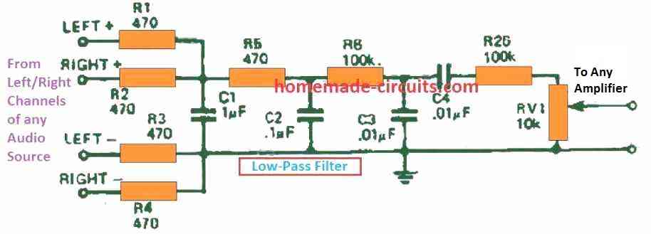
The simplest design will have the low pass filter as shown below in Figure 1 connected to an extra mono or stereo amplifier that is rated 40W or more. This amplifier is then played using a speaker enclosure with a decent bass response.
Another alternative is when the above low pass configuration is implemented with the self contained speaker system that is purposefully designed for bass reproduction as discussed in this article.
Since a spare amplifier may be cumbersome, a simple built-in amplifier as the one used in this project was designed.
Construction
In its most modest form, the booster is used with a separate amplifier. If so, the filter must be made on a tiny piece of perforated board or tag strips.
The whole unit should be assembled within the new bass speaker case (as done with our prototype unit) or any other available place.
This one-piece unit can be easily made as most components are fixed directly on the PCB like shown in Figure 4.
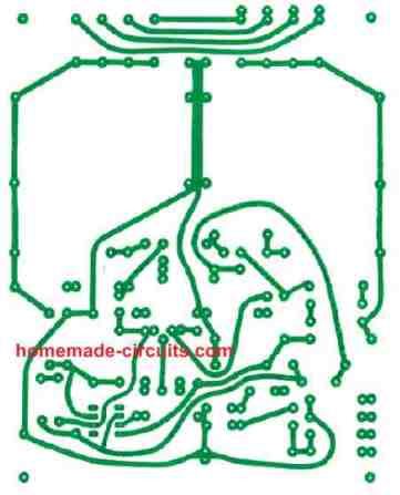
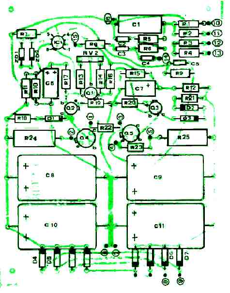
The main power transformer, output transistors and regulation potentiometer are installed externally.
Then, connections are established to and from the components based on the numbers on the PCB layout plan and the schematic.
It must be ensured that all the electronic components are placed according to their correct polarity before soldering.
Transistors Q6 and Q7 are fixed on the heatsink with insulating washers and connected to pins 1, 2, 3, 4 and 5. The connection points are depicted in Figures 2 and 5.
The power transformer must be attached on rubber if the amplifier will be placed inside the speaker enclosure.
Using a shielded cable is advised for making the connection to the inputs and the volume control.
How to Test
Once you are certain all the electronic components are in their right places, set the wiper RV2 in the middle of its travel. Ensure not to connect the speakers at this point.
After that, turn on the main 240 V supply and measure the voltage across the speaker terminals. The value should below 0.2 V and if it's more, switch off the supply and thoroughly examine all the connections.
If you do not have a multimeter, connect one speaker wire to one side of the amplifier output and briefly touch the second wire to the other output point.
On good connections, the speaker will not produce any sound or just a faint “click” sound. If the speaker cone immediately jumps away, turn off the supply and examine the connections again.
If the speaker is silent and everything seem OK, use a milliammeter (if you have it) to measure the current in series with one of the speaker wires.
Fine-tune the potentiometer RV2 until the reading on the ammeter shows 40 mA. If there is no milliammeter, just let RV2 in the middle position.
Next, attach the lead from the current speakers to the filter input and connect the bass speaker to the booster amplifier.
You may power ON the supply and inspect the entire system. Bear in mind that the sound from the bass booster circuit may be a bit distorted if this is utilized from an independent audio source.
However, if you connect the inputs of the circuit with the terminal of an existing left/right speakers of a ready made stereo system, then it might produce a sound incredibly good and with huge bass level.
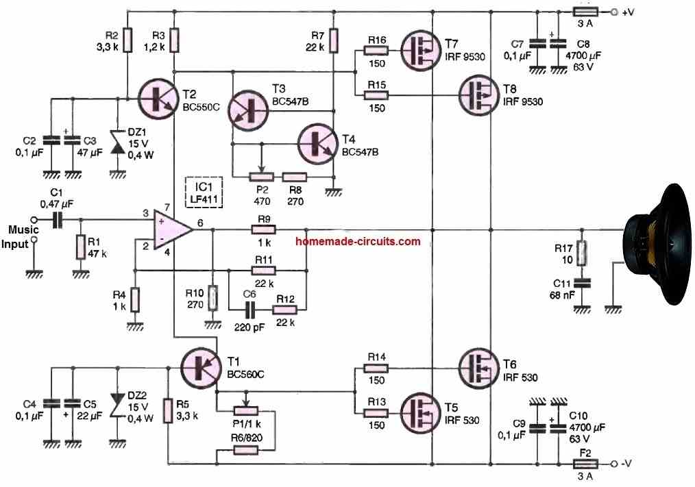
Circuit Description
The complete circuit schematic of the bass booster speaker box system can be witnessed in the following diagram
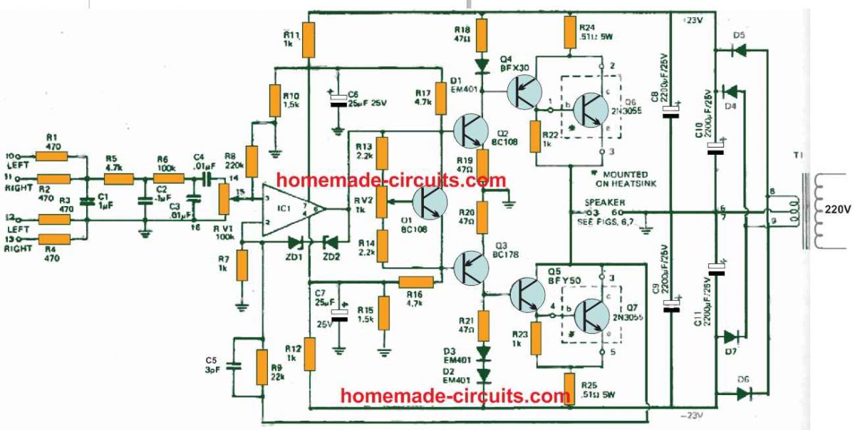
Resistors R1 to R4 combine the output from every channel of the present stereo amplifier.
Then, resistors R5, R6 and RV1, in addition to capacitors C1, C2 and C3 create a low-pass filter with a cut-off frequency of about 200Hz. Moreover, it also has 18 dB per octave slope.
To protect the speakers from switch ON spikes and transients, capacitor C4 functions as a high pass filter with roughly 30 Hz.
Figure 1 displays the filter that is intended for use with different amplifiers has a 20 dB attenuator attached before the output potentiometer. This guards the subsequent amplifier against overloading.
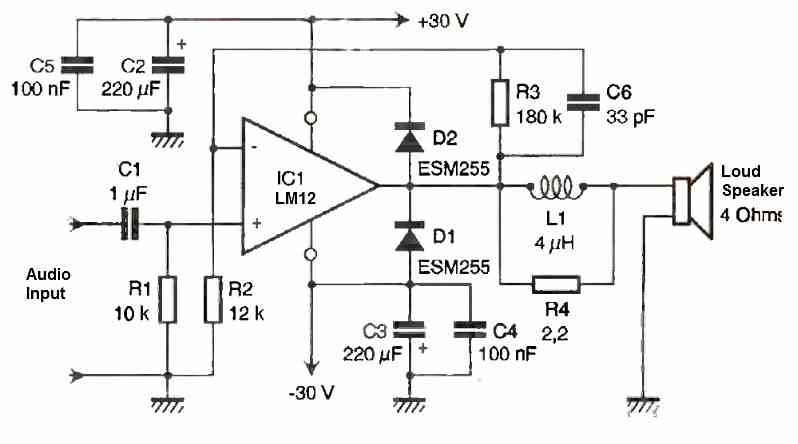
The amplifier in Figure 2 has a voltage gain of 23 .
Additionally, it also outputs around 25 W into 4 ohms and a frequency response in the range of 0 Hz to around 50 kHz.
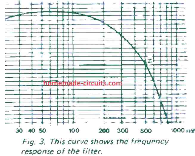
But, when the input filter is added, the frequency response of the amplifier becomes the same that of the filter. Figure 3 shows the curve of the filter response.
The principal voltage gain of the amplifier circuit is supplied by IC1, Q2 and Q3.
Transistors Q4 and Q5 supply the required current gain to trigger the output transistors Q6 and Q7.
While Q1 stabilizes Q2 and Q3, D1 balances transistor Q4. Then, diodes D3 and D4 compensate transistors Q5 and Q7.
By means of restricting the output voltage swing of the IC, Zener diodes ZD1 and ZD2 protect transistors Q2 and Q3.
There is a possibility to use the amplifier discussed in this assignment without incorporating the filter.
This means the electronic component will act as a direct 40 W mono amplifier. If that is the case, one of the diodes, D2 or D3 or both must be relocated on the heatsink.
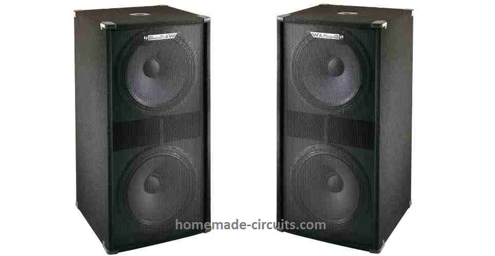
Bass Boost Speaker Enclosure
The case that was evaluated to use with this speaker system is shown in Figures 6 and 7 below.
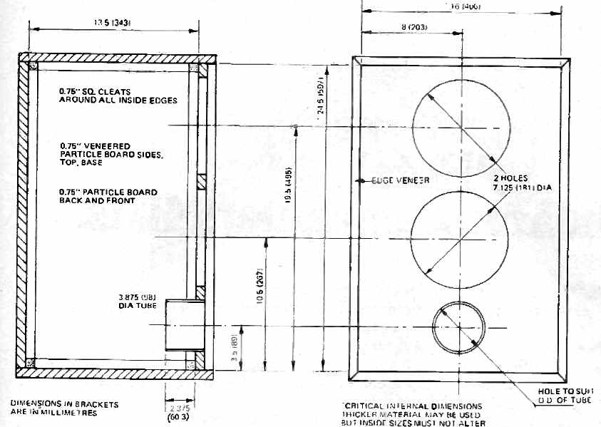
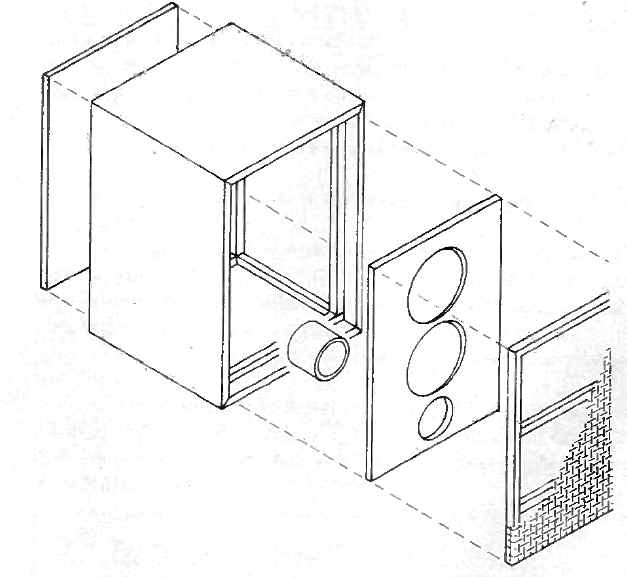
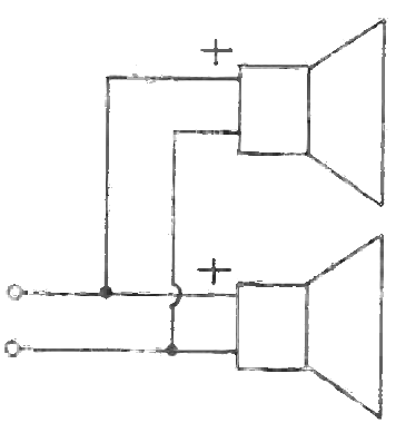
The selected speakers for the bass booster circuit were 2nos 8-ohm Magnavox type 20 W that is parallelly connected. Therefore, the speakers will only have an impedance of 4 ohms.
The speaker enclosure’s internal was covered with absorptive material like foam, on the sides, top and back surfaces.
Speaker wire connection diagram
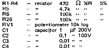
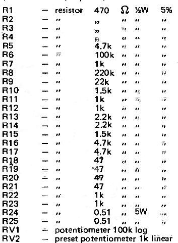
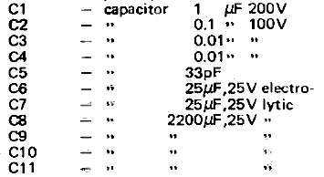
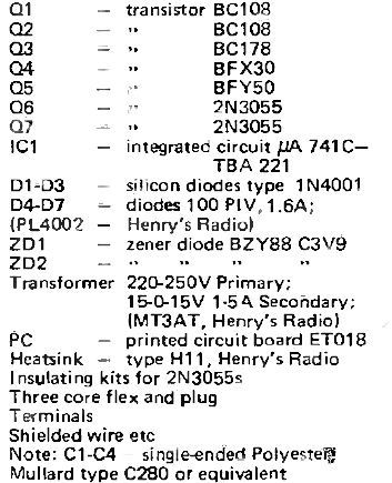
Parts List
Resistors:
Capacitors:
Semiconductors and Miscellaneous

Comments
…with the capacity C4 is everything right?
Why do you think it is not right?