In this post I have explained a simple yet very accurate temperature controller circuit using IC LM35, featuring an automatic cut off with a push button latch.
LM35 is a precision temperature sensor IC, which can be effectively used for detecting temperature differences accurately. For more details regarding this IC you can refer to this article.
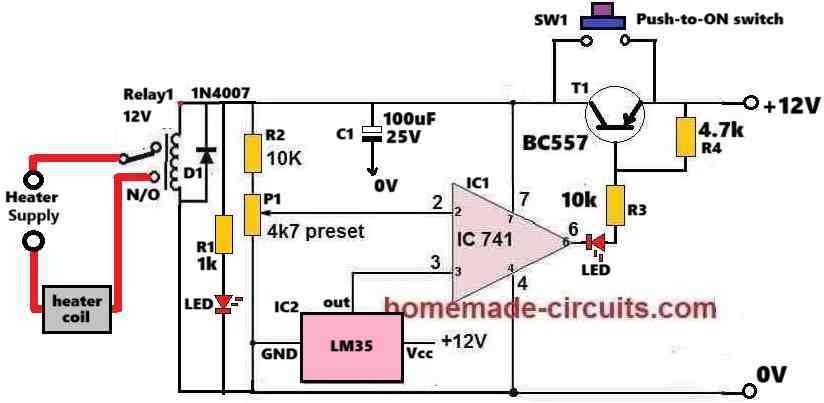
Circuit Diagram
How the Circuit Works
The IC1 741 is configured as a comparator circuit.
Its pin#3 which is its non-inverting input pin, is attached with the output of the heat sensor IC2 LM35.
The inverting input pin#2 of IC1 is configured with a preset P1, which is used for setting the reference voltage at pin#2.
Whenever pin#3 voltage exceeds pin#2 voltage, the IC1 output at pin#6 turn high.
Conversely, as long as pin#3 voltage remains below pin#2 voltage, the output pin#6 of IC1 remains at 0V, or logic low.
At normal room temperature the LM35 output will be low which will keep the pin#3 potential of the 741 lower than its pin#2 reference.
Therefore, when the push button is pressed, the IC741 momentarily activates sending a 0V (low) to the base of BC557 which now conducts so that the whole circuit now gets latched even if the push button is released, and stays powdered through the BC557.
In this situation the relay switches ON and its contacts shift to the N/O points. Since the heater is wired with the supply through the N/O contacts of the relay, it is also switched ON.
The heater temperature now starts rising. Since the IC2 LM35 is attached with the heater, the LM35 also starts heating up which causes its output voltage at pin#3 of IC 741 to rise proportionately.
When the LM35 output voltage at pin#3 of IC1 741 reaches a point where it exceeds its pin#2 potential, the output of IC 741 instantly reverts and goes high.
As soon as the output of IC 741 goes high, it inhibits the negative or 0V supply to the base of BC557. Due to this the BC557 turns off.
As BC557 turns OFF, it breaks the latch so that the 12V supply to the circuit is cut off, the whole circuit along with the relay is turned off.
This also turns OFF the heater and the circuit returns to its previous original condition.
How to Setup and Test
Assemble the circuit as shown in the above diagram. Initially, do not connect any heater with the relay contacts.
Keep the P1 slider fully at the positive level or fully towards R2.
Switch ON the 12V DC to the circuit.
Push and release the SW1 switch momentarily. This should instantly cause the circuit and the relay to switch ON and get latched. Both the LEDs must illuminate.
Next, using a soldering iron heat the LM35 to the desired level. Monitor the temperature with an accurate thermometer, make sure it does not exceed 100° Celsius.
Once the desired temperature is reached, slowly adjust the P1 preset until the IC1 output turns high causing the latch to break and turn OFF the relay. This is indicated by the LEDs which are now turned OFF.
Repeat the above procedure a few times to confirm the results.
The circuit is now set and ready to work with an actual heater attached with the relay contacts.
Troubleshooting
If somehow the circuit does not work, please implement the following improvements in the circuit.
Please connect a 1uF/25V capacitor across the base/emitter of the BC557 transistor. This will ensure that the circuit does not start by itself during power switch ON, rather initiates only when the push-button is pressed.
Please remove R2 (10k resistor) and replace it with a jumper. This will ensure that when initially the slider of the preset is held at the positive side, the op amp output delivers a low logic without fail.
Also, connect a 1uF/25V across pin#3 of the IC and ground, this is optional.
After finishing the above operations, please follow the steps explained under "How to Setup and Test."
Parts List
- All Resistors are 1/4 watt 5% CFR
- 1k, 4.7k = 1 each
- 10k = 2
- 4.7k preset = 1
- Semiconductors
- IC 741, IC LM35 = 1 each
- Transistor BC557 = 1
- LEDs 20mA, 5mm = 2
- Relay 12V 10 amp = 1


Comments
sir I have changed nothing only just a preset I have lowered the value to the 5k and now it’s working! is this good ?
But as per our previous discussions, you were supposed to change the 10k resistor with a 470 ohms so that the MOSFET gate can get proper current, right? And also the 12V zener diode to 15v zener? Anyway, 24V cannot show at pin#3 of the opamp, because we have 12V zener across it. Something’s wrong in your circuit. If 5k preset works for you, you can use it.
hey there 👋🏻 sir how are you ! I have a question right now I’m facing a problem which is why I’m getting 24v maximum at lm358 at pin 3 ? and why the whole circuit is getting turned of at 9v ? previously I never faced this kinda issue but why now ? I have replaced bc546, bd140 and also new ic but then again same issue! why ?
Hey Neeraj, I am good, thank you!
The problem you are facing should never happen, because you already have a 12V or 15V zener after the 470 ohms you changed in place of the previous 10k 1 watt resistor.
That means the 10k preset is connected across this 12V or 15V supply, so how can pin#3 of the opamp get 24V?
Please check the voltage across this zener diode and confirm the results once again…
sir can we include a small series resistor (e.g., 10Ω) in series with each MOSFET gate ? for good current sharing? and if yeah then how ? and yeah I’m going with 15v zener and 470ohm 5w diode
Yes, you can do it in this way: From the gates of each MOSFET connect a 10 ohm resistor, and then join the other ends of the two 10 ohms with the common gate supply input. That’s all!!
no sir I can’t replace mosfets now but can we use 10k 5w or 2w resistor? and 15v zener diode or any other power resistor because serious changes can cause me so much now ! please 🙏🏻
You can use two 1k, 2 watt in parallel, to increase current, if you don’t want to use the extra BJT.
First, try with a single 1k 5 watt, if it works then good, otherwise use two 1k 2 watt in parallel, or use a single 470 ohm 5 watt.
Also, replace the gate zener with 15V zener diode…
So I need to buy 1k 5watt resistor and 15v zener diode? ? and also the resistance value is not too much lower nah ? like from 10 k to 1 k ?
Actually even with 1k, the current will be just 50 ma, which might be not enough to operate the gate of the high current MOSFET….in that case I would recommend using a transistor driver, as shown below….if possible replace the transistor with a Darlington transistor such as TIP122…
https://www.homemade-circuits.com/wp-content/uploads/2025/06/automatic-heater-controller-circuit-with-mosfet-driver-amplifier.jpg
hello sir how are you I hope you’re fine I have a one question why my mosfets are getting crashed all the time I’m using 2 irf540n MOSFETs in parallel as you suggested me with the 12 V zener diode but after sometime one of the mosfets gets faulty but the other one stays perfect this cause circuit malfunction I checked it they gets heat up madly but is there any way so we can solve this issue without heatsink because I heard somewhere that limiting current at the gate of this mosfets can also cause malfunction and heat should we replace current limiting resistance 10k 1w ?
https://www.homemade-circuits.com/wp-content/uploads/2024/07/48V-heater-controller-circuit.jpg
Hello Neeraj,
That’s correct. The 10k 1 watt resistor might not be able to provide sufficient gate current for the MOSFFETs. In that case, yes, please replace that resistor with a 1k 2 watt, or 5 watt wire wound resistor, and also increase the 12V gate zener diode value to 15V, and check the response.
sir please look at the link !
Neeraj,
The circuit diagram for MP4560 is easily available online.
Let me know what more information you need about this device?
For further discussion, please post your comment under the following article:
https://www.homemade-circuits.com/ic-mp1584-datasheet-and-circuit-diagram/
Ok, please disconnect the TTP223 and check it separately, connect an LED with resistor across its output and check its response to touching..
this one sir
sir as you can see above of this comment this is the circuit we were working on last year and now I am getting issues with the touch module !!!!! I’m waiting for your comments please help me
That’s great Neeraj,
Let me know if you have any further problems with the circuit…
Neeraj,
I have answered you under the TTP223 article, please discuss under that article.
Please post the exact image which you are discussing. Right click on the image and click “copy image address” and paste it in your comment…
Hello Neeraj,
Let us discuss the matter under the following article, please post your question here:
https://www.homemade-circuits.com/ttp223-capacitive-touch-module-explained/
hello sir I know it’s been a long time since we talked I hope your are good and healthy i just wanna ask you a thing that! last time we fixed the all issues with the ttp223 but now if I install new one onto the circuit the whole story completely changes ! don’t know how I have tried several ttp223 but still all the responses were same the toggle function of the ttp223 couldn’t proform well it’s stays on whenever I touch it it’s bed how could I fix it ? i/o have 1k to the bc546 ! but still it’s not working at it should have to be !
sir it worked 🎉🎉🎉🎉🎉 after implantation of the 1k with the series of the i/o it worked seamlessly now I am testing it with every condition if I face any issues during testing I will tell you ! thanks sir 👍
sir it doesn’t work at all even after replacing 1k and 4.7k and 10k the results were same as Before sir I have a little doubt if I push manually bd140 the circuit works and if I touch ttp223 is also works and led blinks whenever I touch it ! i checked the voltage across vcc and gnd pin of the ttp233 we got 5.4 v after the circuit was not before thats means if we wanna to operate this touch module as a push button then we have to make any changes so that we can get voltage to this module before we start the whole circuit! understood? can we connect the zener of this ttp223 directly to the input of the circuit? at the emitter of the bd140? as my assumption this will provide ttp223 5v and this ttp223 can start circuit! !
Since we already have a 10k resistor in series with the VCC pin of the TTP, so it may be fine to connect the I/O output of TTP directly with the BC546, however I would still recommend using a 1k in series between th I/O and BC546 base.
Please check the results and let me know.
yeah sir I removed the 10k resistor and then I checked voltage in gnd and i/o this whole ttp223 workes on 3v or 2.7 v and I got 2.5 v at the i/o pin should I connected this i/o directly to the bc546 base ??
I have followed this circuit diagram!
https://www.homemade-circuits.com/wp-content/uploads/2024/07/touch-controlled-heater-controller-circuit.jpg
so can you show me the modifications on the diagram ? because of the diagram I can understand it easily please 🥺
in simple terms can’t we reduce the input voltage for ttp223 to 3~5v and then directly connect it’s i/o pin to the base of bc546. it will be less complicated and also we can use power resistor to reduce voltage just like we did with our ic lm358 ! ????
but how we can use simply with 10k resistor?
but it’s too complex! can’t we make it more straight and simple?
last time i tested this circuit which you have provided me long ago !
https://www.homemade-circuits.com/wp-content/uploads/2023/12/how-to-connect-capacitive-touch-switch-TTP223.jpg
with this ttp223 was able to work with my conditions also with 5mm thick plastic sheet!
yeah sir it worked i have tested it with some distance!
Neeraj, Please disconnect the 10k from the I/O of the TTP and check the voltage directly between the I/O and GND. The voltage here should be around 0V in normal condition, and should turn 5V momentarily when you touch the TTP touch-pad.
If you are not getting 5V after touching the touch-pad that means your TTP has some problems, then you must diagnose the TTP separately.
Yes 0.7V is required to switch ON any BJT.
sir now we are getting 5.4 v in the input of the ttp223 and still the circuit is not getting started because in the i/o pinout the voltage ttp223 is producing only 0.22v and this cause us ! if I use mannual option and monitor voltage at base of the bc546 then I got around 0.75 to 0.77v ! you have suggested me to connect 10k resistor at the i/o pin to base of the transistor if we monitor voltage at the i/o pin above the resistor we got 0.4v ! we need to trigger the bc546 then we need 0.7 v atleast! am I right?
Actually the BC547 can be removed and the ttp223 output can be directly connected with the base of BC546 transistor through a 10k resistor…
It is the most basic configuration, and all the parts included in it are necessary.
Neeraj, You are absolutely right, I completely missed that point.
Yes the TTP223 module’s Vcc must be supplied directly from the 48V DC input so that its output can provide the triggering voltage to the BC546 base.
So, in the following diagram, please disconnect the TTP223 1k from the 12V zener diode. Then replace the 1k with 10k and connect it with the +48V supply, make sure the 5V zener remains connect across the Vcc and ground of the TTP223:
https://www.homemade-circuits.com/wp-content/uploads/2024/07/48V-heater-controller-circuit.jpg
You can modify it in the following manner:
https://www.homemade-circuits.com/wp-content/uploads/2024/07/48V-heater-controller-circuit.jpg
If it has problems, try replacing the 1k associated with the 5V zener with 4.7k or 10k.
Neeraj, Please do only the following modifications, without changing anything else:
For the opamp circuit, replace both the 5V zener diodes with 12V zeners, and supply the TTP223 with a separate 4.7k/4.7V zener diode across its VCC pin, as done in the original diagram:
https://www.homemade-circuits.com/wp-content/uploads/2023/12/how-to-connect-capacitive-touch-switch-TTP223.jpg
sir it didn’t worked! I have replaced 12v both zener to 5v and connected 4.7k ohm to the bc546 but still the ttp223 is not working if I touch bd140 manually and then ttp223 while the circuit is on the ttp223 module will be illustrated for some seconds and also whole circuit is not working as it was working with 12v zener there’s no voltage at the pin 2 and 3 of the ic and if I touch bd140 manually the circuit will on and then I remove my twizzer circuit will turned off !
can we connect bc546 base with the ttp223 ? or with the copper plate ! ?
The ground side 1k resistor at the BC546 base must be replaced with a 4.7k resistor….
You can try the following modified heater controller design with touch switch…..both the zener diodes are now 5v zener diodes:
https://www.homemade-circuits.com/wp-content/uploads/2024/07/touch-controlled-heater-controller-circuit.jpg
That’s exactly what I suggested in my earlier reply.
You can connect the TTP223 output directly with the base of BC546 through a 10k resistor.
The +5V can be extracted directly from the opamp supply pin by replacing the IC zener diode with a 5V zener diode.
Sorry i did not understand your question…where do you want to connect the 10k?
Ok, then you can connect the 1N4148 end which is shown as “to BC557 base” to the base of BD140.
Neeraj, please provide more information regarding how you tested the module?
First confirm the TTPP223 capacitive touch distance with an LED, whether it works as per your your specifications or not, then we can configure it with the BC546. Copper plate will get triggered with other external RF disturbances, so it is not good.
Another way is to use two or three BC546 BJTs and connect them in Darlington form and then connect first transistor base with a wire whose end can be terminated with a large plate. If you bring your hand close too this plate then the circuit will be triggered,
But the problem is, this type of circuit can also get triggered by external RF interference and RF noise.
yeah sir the base of bc546 worked but the real issue is can we make capacitive touch function? because the circuit will be behind 5mm thick plastic sheet and this bc546 can’t make it happen ! I know ttp223 will be problematic but can’t we find another way to make it possible?