In this post I will show how to construct LED strip controller circuit using Arduino, which can turn ON/OFF and decrease/increase brightness of LEDs using ordinary IR (Infrared) remote.
What is LED Strip Light? (For noobs)
If you are not familiar with LED strip lights, let’s understand what it is.
LED strips (sometimes called as ribbon lights) are flexible PCB which consists of series of bright LEDs and controller circuits, the components on LED strip are surface mounded (SMD).
It is used for decorating homes, party rooms and outdoors during festival seasons etc.
It has sticky layer on back side which can stick on walls, wood or any smooth surface without need of adhesive.
It comes at various lengths, width, colours, in this project we are going to control single colour LED strip. But if you want control RGB colours individually you may modify the given code and circuit.
LED strips work at 12V or 24V depending on the specification but, in this project 24V is not suitable as arduino board is not designed to handle 24V. USB type LED strips are also available which can operate at 5V and can be used in this project only after proper modification of the circuit.
By now you would have understood about LED strip Light.
LED strip Light need controller circuit which are readily available on market but those are expensive. In this project we will construct simple and inexpensive circuit which can control LED strip lights via any IR remote.
Circuit Diagram:
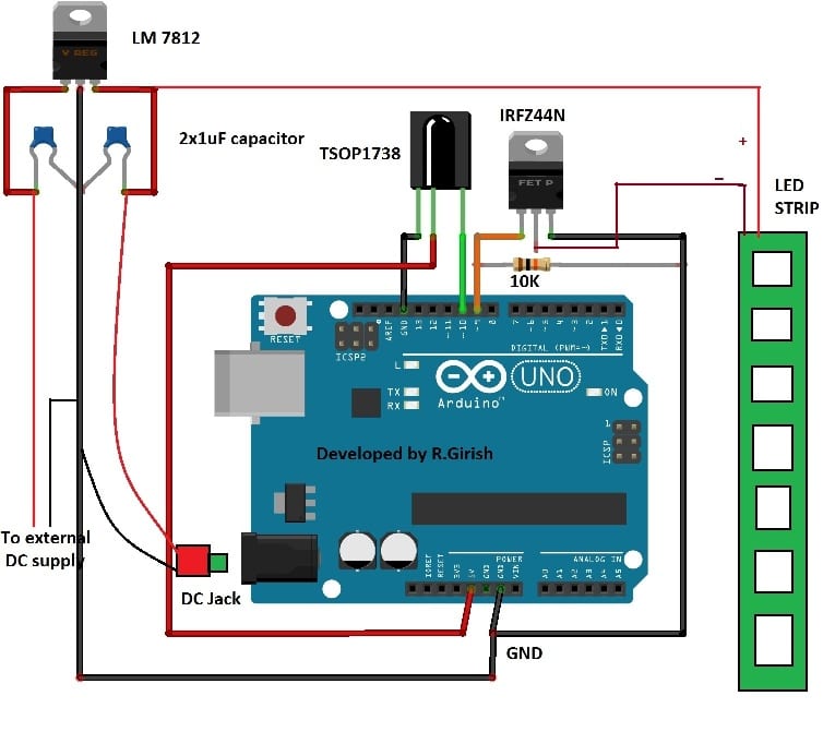
The circuit consists of few components: voltage regulator with coupling capacitors, TSOP1738 IR sensor, MOSFET IRFZ44N, LED strip and brain of the project arduino Uno. You can choose your favourite arduino board for this project.
The TSOP1738 sensor receives IR signals from the remote and decode in such a way that microcontroller can understood. The N-channel MOSFET amplify the signals from arduino and fed to LED strip.
The voltage regulator powers arduino and LED strip. Make sure your power supply can deliver adequate amount of current for LED strip.
The proposed circuit is designed for 12V LED strips, you can change voltage regulator depending on LED strip specification. It is advised not to use a LED strip which has voltage rating higher than 20V, as arduino’s absolute maximum is 20V.
This circuit can turn on and off the LED strip; it can adjust brightness up and down by 5 steps, this is achieved by applying different PWM signals to LED strip.
How to Test
To accomplish these operations follow the instructions given below:
• Choose any 3 buttons on your remote which you are going to control the circuit. We need to know the hexadecimal code for these buttons
• Open IDE, go to file>examples>IRremote>IRrecvDemo.
• With completed setup connect the USB to arduino and PC (without external power) upload the code and open serial monitor.
• Now press each buttons once, you will see its hexadecimal code on serial monitor and note it down. These hexadecimal code need to be uploaded with the given program to arduino.
NOTE:
The proposed circuit is designed for controlling single colour LED strip. If you have multicolour LED strip short RGB terminals (gives white colour), rest of the circuit is same.
Program Code:
//---------Program developed by R.Girish---------//

#include <IRremote.h>

int X;

int Y;

int output = 9;

int W = 5;

int receive = 10;

IRrecv irrecv(receive);

decode_results Z;

void setup()

{

irrecv.enableIRIn();

Y=0;

X=255;

pinMode(output,OUTPUT);

}

void loop()

{

if (irrecv.decode(&Z))

{

if (Z.value==0x80C) // Hex code for ON/OFF

{

if(Y==0)

{

digitalWrite(output,HIGH);

Y=1;

}

else

{

digitalWrite(output,LOW);

Y=0;

X=255;

}}

if (Z.value==0x811 && Y==1) // Hex code for reducing Brightness

{

if(X-255/W<0)

{

analogWrite(output,X);

}

else

{

X=X-255/W;

analogWrite(output,X);

}}

if (Z.value==0x810 && Y==1) // Hex code for increasing Brightness

{

if(X+255/W>255)

{

analogWrite(output,X);

}

else

{

X=X+255/W;

analogWrite(output,X);

}}

irrecv.resume();

}}

//---------Program developed by R.Girish---------//
NOTE:
Replace 0x80C, 0x810 and 0x811 with your remote’s hexadecimal code starting with “0x”