Pets and kids (under 4) have one thing in common, they are curious by nature and love venturing into unknown zones ending up in some sort of mess or trouble. Pet or kid tracker equipment which are quite similar to a key finder circuit were specifically designed for solving this issue, here I have explained how these work and how to build one at home. The idea was requested by Mr. Akmar.
Key Finder using 433MHz RF Modules
thank you for posting this article..:) I really like it.
For your information, I want to build an object finder (ex:key finder) similar to this circuit and I will modify it a bit sing 433MHz RF modules..the idea is when the receiver receives signal from the transmitter, it can produce sound if it detects the object..
if possible, can I substitute the load with a buzzer? thank you and I hope you can help me with this.
Akmar
The Design
The requested application of a keyfinder is similar to what we normally do when one of our cell phones become untraceable in our home, we then resort to calling it through another phone so that it rings and identifies its location.
However when it comes to some other equally important item such as a key which has no calling feature to respond, locating it becomes hugely difficult and frustrating.
A simple remedy for this may be to attach some kind of a wireless device to the key chain so that whenever a misplacement of the thing occurs, the owner is able to quickly find it by connecting it through a matching transmitting handset.
The handset transmits the matching frequency forcing the attached key receiver to beep or produce the programmed sound for identifying itself.
The above concept may be also applied for tracking or monitoring purpose, for example on pets or small kids. Here the transmitting device could be attached to the member so that whenever the member tends to move out of a predetermined safe premise, the owner or the parent is instantly notified about it through an alarm over a nearby or a pocket receiving device
Keeping a continuous watch over these elements may not be always feasible for all and therefore resorting to some kind of hi-fi device becomes a favorite alternative.
Below we see two diagrams which can be tried for the proposed pet finder or tracker and also for monitoring and restricting kids in parks or in building safe premise.
The heart of the circuits are the standard 315MHz RF modules that come in compatible packages as Tx/encoder and Rx/decoder.
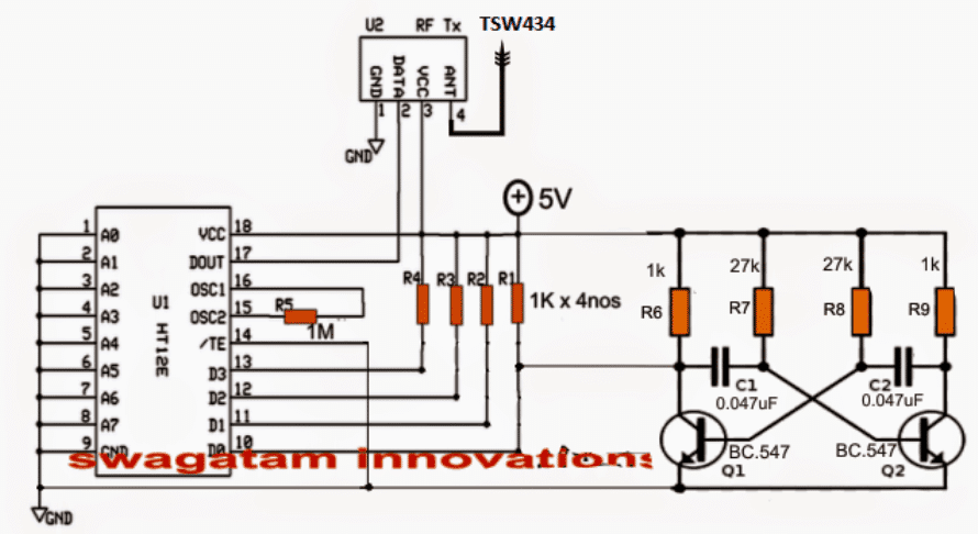
The first diagram shows a Tx (transmitter) and its encoder module. The HT12E is the encoder chip while the upper small chip is the RF transmitter.
The Transmitter Circuit (Tx)
The function of the Tx chip is to generate the 315 MHz carrier signals and modulate it with the applied digital or an analogue data via its relevant pinouts.
This data must first go through a processing phase in order to make the data recognizable to the Tx chip. The digital or analogue input could be from an external source such as a PC USB, a sensor device or simply from an oscillator as used here.
The data is fed to one of the inputs of the encoder (since we have four inputs/outputs for this model, we may choose any one of these for the intended actions).
The diagram shows D0 being used as the input for the data feed, the data feed here is nothing but an ordinary square wave oscillator using a standard transistorized oscillator circuit consisting of Q1, Q2 and the associated parts.
The frequency from the astable constantly switches the encoder which in turn processes this signal and feeds it to the data input of the Tx.
Tx now makes sure that this data rides over the 315MHz carries and is transmitted into the atmosphere for enabling the Rx module in the vicinity to capture and reprocess these signals into the required tracking info.
An oscillating frequency is used as the trigger instead of a fixed switching to minimize current consumption of the Tx unit and ensure a much longer battery life.
The battery here could be a small 3V button cell, the entire circuit could be built using SMD to make the configuration as small as possible.
Transmitter Schematic
The above system would be rather incomplete if it's not complemented by an Rx (receiver) circuit. The following circuit highlights the receiver system which works exactly in the same way as its Tx counterpart but in an opposite manner.
Here, the Rx chip is stationed for capturing the data sent by the Tx module. The captured data is mingled with the 315MHz carrier waves and is in an encoded form, therefore it must go through a reprocessing, which is done by the HT12D chip via its pin14 (data feed).
The Receiver Circuit (Rx)
The processed signal is anticipated across the relevant output pin of the decoder and terminated to produce a high or a low logic signal or as per the original data content.
In the discussed pet finder/tracker or the key finder circuit we have used D0 as the I/O pins for both the modules, therefore in the following Rx module we find D0 being hooked up with an external transistor buzzer driver stage.
The processed square wave output at D0 is now used for triggering the first BC557 transistor, which responds to these signals by staying continuously ON due to the inclusion of the base 330 ohm resistor and the filter capacitor 4.7uF stabilizing components.
As long as the first PNP stays ON, the second PNP is restrained from activating and keeps shut off but only for so long as the Tx module is within the transmitting range.
Once the Tx module which may be fixed on the kid or the pet drifts out of the predetermined safe zone, the RX module is inhibited from the signals. When this happens the second PNP gets a chance to trigger ON activating the attached buzzer.
The alarm sound instantly notifies the owner or the parent regarding the situation.
Receiver Schematic
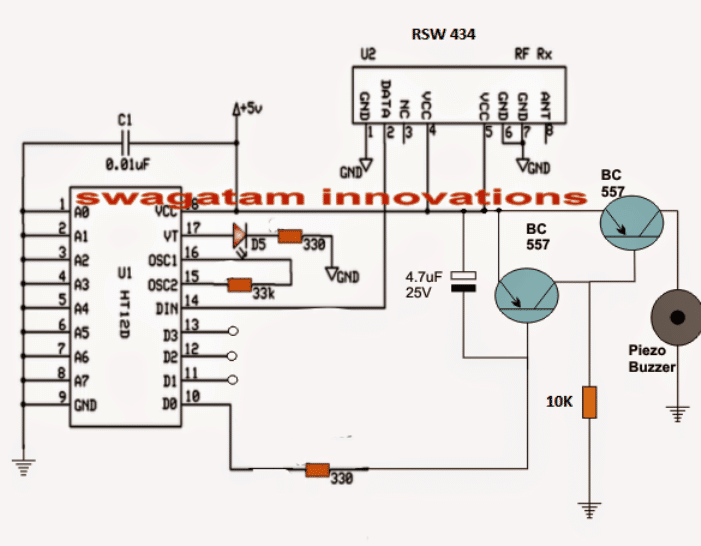
In order to use the above circuit as a key finder, the right side BC557 will need to be removed and the buzzer replaced with the shown collector resistor of the left BC557.
Also Tx circuit will now need a switch for the required toggling and detection of a buzzing sound from the above Rx attached key circuit.

Comments
sir when the object is moving out of range buzzer is ON but again suddenly when the object is inside the range buzzer sound is not OFF again we are switching off the power supply and then buzzer is OFF. we don’t want that we need to reset it automatically
Pranitha, to solve this you can operate the RX with a oscillating DC supply instead of a constant DC, use a IC 555 base astable circuit having a frequency of arounf 2Hz, and connect the Rx circuit across it pin#3 and ground for powering it.
sir thank you its working but we want to reset the circuit automatically so can u please tell us about that and will u please say briefly about the main principal of dis project?
I am glad it is working, What kind of reset are you referring to? The circuit does not require any resetting, the buzzer is supposed to switch ON when the Tx is out of range and switch OFF when it comes back within range
Sir plzz can u plzz mail ur mobile number to clarify our doubts
Pranitha, you can discuss here as much as you want, due to my busy schedule phone conversation may not be possible.
Sir can u provide us kit directly ?
kit will cost you Rs 3500/- better to build one instead
thanku so much sir fr clr xplanation.nd one mre doubt.
v have connectd as per ur ckt diagrm so nw v want to test our ckt whether it is crct or not how do v check that our ckt is wrkng properly r not ? plzz guide us sir since v r dng our projct.
Pranitha, in the receiver schematic, connect an LED in series with the 330 ohm resistance at pin#10. Cathode will be towards pin#10, anode towards BC557….you can connect this LED on right side of the 330 ohm or at the left side, it doesn’t matter.
when you switch ON the transmitter, you must see this LED glowing, and the buzzer should be silent.
however this will only happen if the transistor oscillator circuit connected with the transmitter is working correctly
tq sir. how it relates to real situations like child tracker or key finder ….can h plzz help us sir
as long as the Tx is within the range, Rx will be receiving the signals and this will keep the connected buzzer switched OFF, but the moment the Tx is taken out of the range of Rx, Rx will stop getting the signals and the buzzer will start ringing or buzzing…
sir if i want an 10 mts long distnce how much does the antenna wire should be
for 10meter range do not use any antenna, if it doesn’t work then try a 1 inch long wire as the antenna and check the response
Can we use 434mHz RF module ?And how can we vary the range ?
We are not getting buzzer at collector of right side transistor ? Sir can u plzz help us
Pranitha, you can use any RF module for creating this circuit, the range can be roughly tweaked by changing the antenna wire length, there’s no other way of varying it as far as I know.
Sorry I did not understand what you meant by: we are not getting buzzer at the right side of the transistor? please clarify
sir can u plzz provide us video of above ckt
I am sorry video may not be possible, but I can help you to complete the project with step wise tutorial.
dear sir,
how should the antenna be chosen ?
ive tried this circuit on a bread board..but doesnt work.
is the led supposed to turn on when supply is given??
Maria, the antenna can be made by using a small piece of flexible wire.
On breadboard you can make mistakes, so it is never recommended for high frequency RF circuits, you should build it by soldering on a well designed PCB or a veroboard.
the LED will blink on signal reception from the Tx circuit.
build it stagewise, first confirm the Rx/Tx circuits using only with LEDs, once you succeed with that then you can proceed with the external BJT circuits.
Sir, here you have used a RF module, so instead of that will i be able to use a bluetooth based module as Tx/Rx ? if so may i know the changes that will occur in the circuit? and what are the new components that i have to buy.
thank you 🙂
Shashini, You will just need to replace the Q1/Q2 stgae from the first circuit and associate it with your Bluetooth headset Mic wires.
for the receiver you won't have to do anything, since the tone from the above modified Tx could be directly heard on the Bluetooth headset speakers, however this tone would be in the form of a continuous tone.
Could it be possible if i make 1 transmitter, with 3 different independent receivers?
I am not sure about that, you'll have to check it online.
Noted sir. But are there any alternative components for TSW and RSW 434?
you just have to make sure that the pins A0 to A9 are configured identically for all the modules…this will ensure that all Rx modules respond simultaneously to the Tx signals
Thank you for your reply sir. Pardon me but i'm still a novice at this, but how can i make that possible? If i push a specific button for Rx1 at the Tx, the only the Rx1 will buzz. Hope u get the idea, help me sir. Thank u for ur generosity. Pls teach me sir
Hi Mharlee, yes 1 Tx and multiple number of Rx is definitely possible…
Good day sir. May i know if this circuit is working? And, can i make 3 pairs of transmitters and receivers? if yes, do i need to change some components? Because i think that the components in this circuit share the same frequencies right?
hello sir i am going to build one, can you please give me the specific names of components to buy, thank you, sorry newbie here
I can't see any D1, D2, D3 in the circuit??
sir where should i connect D1,D2 and D3
thank you sir
Hello Michael, please copy the part name exactly as shown in the diagram and show it to the dealer, he will be able to provide them all correctly….
Hello sir! I have some queries about this circuit. What is the approximate range of distance for which this circuit works? What kind of oscillator is being used in transmitter circuit?
Is there any speciation on the rf tx and rx module that we have to use here?
Hello Prabhakar,
the range is within 50 meters, the oscillator is RF based, there are many versions of these Rx/Tx modules, each having its own unique range and specifications…any of those can be used for the mentioned application
Hello sir, I am just curious if you have a key finder circuit similar to this, that would be in need of manual programming?
Hello Portgaz, I am sorry presently I do not have a programmable circuit, if I find one I'll surely share it with you.
Hello sir! Sorry to disturb u again. In one of ur replies to others, u hav said tat for the led n buzzer to turn ON the extreme bc557 is removed and buzzer must be connected in the place of collector resistor. Does tat mean, the 10k resistor u asked me to take must be replaced with buzzer?? Also how the antenna must be chosen??
Hello prabhakar, yes you assumed it right…the 10k will need to be replaced with the buzzer.
Hello sir. Me n my friends hav decided to make this key finder circuit as our mini project. Can u please tell us what ics should we use for the circuits. Also what is the value of the resistor near BC557 in the receiver circuit??
Hello prabhakar,
the IC details can be found here:
https://www.homemade-circuits.com/2011/12/rf-remote-control-encoder-and-decoder.html
the BC557 resistor can be a 10k
Hello sir. Iam shylaja, btech ece 2nd year student. Me and my friends hav decided to make this key finder circuit as our mini project. Can u please tell us what ics should we use for the circuits. Also what is the value of the resistor near BC557 in the receiver circuit??
D5 should blink only when the transmitter is ON according to my knowledge. Please disconnect pin4 of RSW434 from 5V supply and check again
D5 keep blinking whenever the receiver turn on even though the transmitter is off. Is it the Q1 for transmitter or receiver that I need to short? And I used 6V battery for the circuit. Is this to high? Also is filter capacitor the same as electrolyte capacitor? I try google this but still I don’t understand
Thank you for your response. I do it practically with the real parts by soldering on PCB board. Maybe I should try building another new one. Another question, is the RF modules used 315MHz or 434MHz? I used 434MHz since it was written in the picture.
Hi Mai, Is the receiver D5 LED blinking? If not then it may not receiving the transmitter pulse…to confirm this you manually short the Q1 emitter/collector and check whether this activates the D5 blinking in the receiver module or not. If not then your transmitter modules or the receiver has problems.
Frequency cannot be an issue as long as both Tx and Rx are from the same set and compatible with each other.
Hi Mai, did you build the circuit practically or through simulation? Please build it practically using real parts, it will work!
Hi Sir. I am trying to do as Akmar did but when I turn on the receiver, the buzzer will turn ON. I have checked the connections many times and even ask my friend to check for me but still no changes. Is it possible that the problems come from the RF module and can I know is there any way to troubleshoot RF module? And I also hope you can give any advice to me regarding this problem. Thank you.
Hi, the indicated Tx, Rx ICs are ready made pre-programmed ICs which require no manual programming.
More info about these remote control modules is furnished in this article:
https://www.homemade-circuits.com/2011/12/rf-remote-control-encoder-and-decoder.html