• Skip to main content
  • Skip to primary sidebar

Homemade Circuit Projects

Need circuit help? Post them in the comments! I've answered over 50,000!

Blog | Categories | About | Contact | Calculators-online
You are here: Home / Datasheets and Components / IC 4013 Datasheet, Pinout Details

IC 4013 Datasheet, Pinout Details

Last Updated on February 24, 2023 by Swagatam 2 Comments

IC 4013 is a CMOS-based dual D-type flip-flop integrated circuit. It is widely used in digital circuits for applications such as counters, shift registers, and control circuits. Below is the detailed datasheet for IC 4013.

Table of Contents
  • Pin Configuration:
  • Electrical Characteristics:
  • Functional Description:
  • Application:

Pin Configuration:

4013 IC datasheet

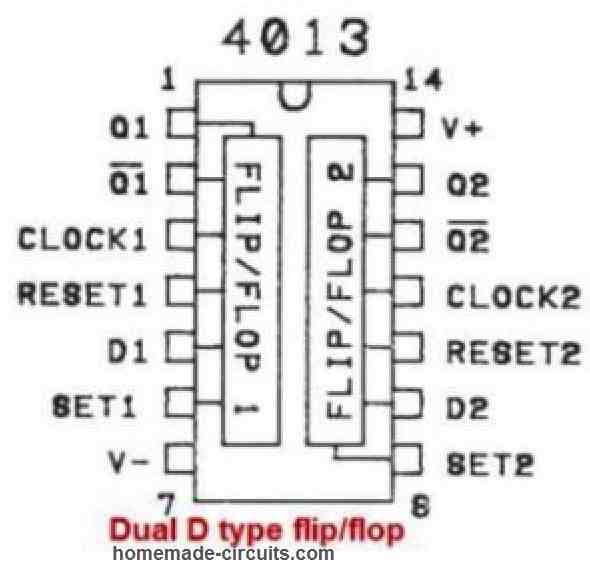
IC 4013 has a total of 14 pins.

The pin configuration is as follows:

Pin NamePin #TypeDescription
VDD14PowerThis pin is the Supply Voltage (+3 to +15V) input of the IC
GND7PowerThis pin is for supplying Ground (0V) input
Q1, Q21, 13OutputThese pins generate the Output from the two D Flip-Flops
Q1, Q22, 12OutputThese pins generate Inverted outputs from the two D Flip-Flops
CLK1, CLK23, 11InputThese pinouts are for supplying the Clock input for the two D Flip-Flops (Rising Edge)
D1, D25, 9InputThese pinouts are D (data) inputs for the two D Flip-Flops
S1, S26, 8InputThese pinouts can be used to Preset the Flip-Flop output to 1
C1, C24, 10InputThese pinouts can be used to Reset the Flip-Flop output to 0

Electrical Characteristics:

  • Supply Voltage: 3V to 18V
  • Maximum Quiescent Current: 5µA at 15V
  • Maximum Operating Current: 3mA at 15V
  • Maximum Power Dissipation: 500mW
  • Input Voltage High Level (VIH): 3.5V to 18V
  • Input Voltage Low Level (VIL): 0V to 1.5V
  • Output Voltage High Level (VOH): 90% of supply voltage
  • Output Voltage Low Level (VOL): 10% of supply voltage
  • Operating Temperature Range: -55°C to +125°C

Functional Description:

A circuit that can store one bit of data is called a D flip-flop. It may either provide HIGH or LOW output.

As the clock switches from LOW to HIGH, the output adapts to whatever is on the data (D) input. Also referred to on the rising edge of the clock. (Some D flip-flops, on the other hand, alter on the falling edge.)

The D flip-flop only analyzes what is on the data (D) input at the precise instant when this transition occurs, according to this.

Certain D flip-flops only alter their output when the clock swings from HIGH to LOW because they have an inverted clock input. On the falling edge is the term used to describe this.

Furthermore, the CD4013's D flip-flops feature Set (S) and Clear (C) pins. Irrespective of the clock, these can be utilized to either reset the output to LOW or set it to HIGH.

Application:

IC 4013 is commonly used in digital circuits for various applications such as:

  • Counters
  • Shift registers
  • Control circuits
  • Frequency dividers
  • Timers
  • Flip-flop circuits

An example circuit of the IC 4013 can be seen in the following figure:

IC2B40132Bflip2Bflop2Bset2Bup2Bcircuit

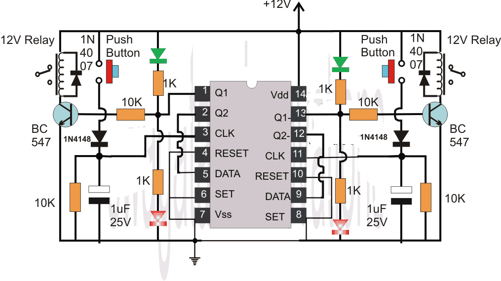
The relay on both side of the IC 4013 can be switched ON/OFF by pressing the associated push button.

More explanation can be found in this flip flop article

In conclusion, IC 4013 is a versatile and often used in digital circuits because of its low power consumption, strong noise immunity, and simplicity of usage.

You'll also like:

  • 1.  IC 4027 Datasheet, Pinout Working, Application
  • 2.  IC 4049 Datasheet, Pinout Function, Application
  • 3.  LM324 Quick Datasheet and Application Circuits
  • 4.  IRF640 Datasheet [200V, 18 Amp N-Channel MOSFET]
  • 5.  IC 4033 Pinouts, Datasheet, Application
  • 6.  Types of Capacitors Explained

Filed Under: Datasheets and Components Tagged With: 4013, Datasheet, Details, Pinout

About Swagatam

I am an electronics engineer and doing practical hands-on work from more than 15 years now. Building real circuits, testing them and also making PCB layouts by myself. I really love doing all these things like inventing something new, designing electronics and also helping other people like hobby guys who want to make their own cool circuits at home.

And that is the main reason why I started this website homemade-circuits.com, to share different types of circuit ideas..

If you are having any kind of doubt or question related to circuits then just write down your question in the comment box below, I am like always checking, so I guarantee I will reply you for sure!

Previous Post: « How to Connect Resistors in Series and Parallel
Next Post: IC 4016 Datasheet, Pinout Function »

Reader Interactions

Comments

  1. Terry says

    May 9, 2023 at 2:42 am

    Can i use a 4013bc in place of a 4013be ic chip. it is for a sump pump controller.

    Reply
    • Swagatam says

      May 9, 2023 at 9:23 am

      You can use it….

      Reply

Need Help? Please Leave a Comment! We value your input—Kindly keep it relevant to the above topic! Cancel reply

Your email address will not be published. Required fields are marked *

Primary Sidebar


Subscribe to New Posts

Categories

  • Arduino Projects (88)
  • Audio and Amplifier Projects (132)
  • Automation Projects (17)
  • Automobile Electronics (101)
  • Battery Charger Circuits (83)
  • Datasheets and Components (104)
  • Electronics Theory (143)
  • Free Energy (37)
  • Games and Sports Projects (11)
  • Grid and 3-Phase (19)
  • Health related Projects (25)
  • Home Electrical Circuits (12)
  • Indicator Circuits (14)
  • Inverter Circuits (88)
  • Lamps and Lights (142)
  • Meters and Testers (69)
  • Mini Projects (46)
  • Motor Controller (64)
  • Oscillator Circuits (27)
  • Pets and Pests (15)
  • Power Supply Circuits (108)
  • Remote Control Circuits (50)
  • Security and Alarm (64)
  • Sensors and Detectors (101)
  • Solar Controller Circuits (59)
  • Temperature Controllers (42)
  • Timer and Delay Relay (49)
  • Transmitter Circuits (29)
  • Voltage Control and Protection (37)
  • Water Controller (36)

Tags

Alarm Amplifier Application Arduino Automatic Battery Charger Circuits Control Controlled Controller Current Datasheet DC Detector Digital Driver Electronic Explained Explored Generator High Indicator Inverter Lamp LED Light Meter Motor Pinout Power Regulator Remote Sensor Simple Single Solar Supply Switch Timer Transistor Voltage Water Watt Working


Other Links

  • Privacy Policy
  • Cookie Policy
  • Disclaimer
  • Copyright
  • Videos
  • Sitemap


People also Search

555 Circuits | 741 Circuits | LM324 Circuits | LM338 Circuits | 4017 Circuits | Ultrasonic Projects | SMPS Projects | Christmas Projects | MOSFETs | Radio Circuits | Laser Circuits | PIR Projects |

Social Profiles

  • Twitter
  • YouTube
  • Instagram
  • Pinterest
  • My Facebook-Page
  • Quora
  • Stack Exchange
  • Linkedin


  • Recent Comments

    • Swagatam on 10 Simple LED Chaser Circuit Diagrams Explained [Knight Rider, Scanner, Reverse-Forward, Cascaded]
    • Sparks on 10 Simple LED Chaser Circuit Diagrams Explained [Knight Rider, Scanner, Reverse-Forward, Cascaded]
    • Swagatam on Regulated Car Battery Charger Circuit for Garage Mechanics
    • Swagatam on 10 Simple LED Chaser Circuit Diagrams Explained [Knight Rider, Scanner, Reverse-Forward, Cascaded]
    • MOSES on Regulated Car Battery Charger Circuit for Garage Mechanics

    © 2025 · Swagatam Innovations