In this post I will comprehensively explain how to use any opamp as a comparator in a circuit for comparing a input differentials and producing the corresponding outputs.
What is an Op amp Comparator
We've been using an op amp IC probably since we started learning electronics, I am referring to this wonderful little IC 741, through which virtually any comparator based circuit designing becomes feasible.
Here we are discussing one of the simple application circuits of this IC where it is being configured as a comparator, no surprise the following applications can be modified in numerous different ways as per the user preference.
As the name suggests, opamp comparator refers to the function of comparing between a particular set of parameters or may be just a couple of magnitudes as in the case.
Since in electronics we are primarily dealing with voltages and currents, these factors become the sole agents and are used for operating or regulating or controlling the various components involved.
In the proposed op amp comparator design, basically two different voltage levels are used at the input pins for comparing them, as shown in the below diagram.
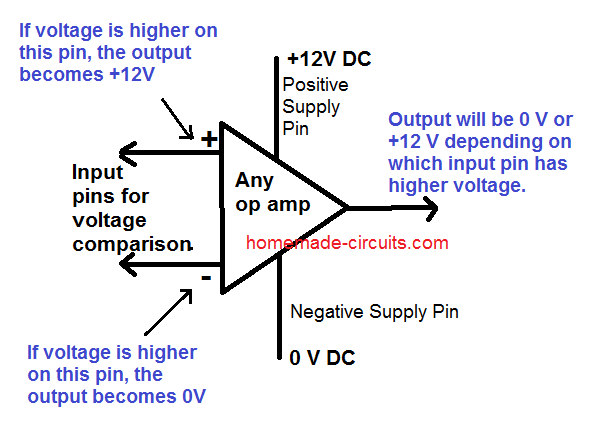
The two input pins of an op amp are called the inverting (with a minus sign) and the non-inverting pin (with a plus sign) become the sensing inputs of the op amp.
When used as a comparator, one of the pins out of the two is applied with a fixed reference voltage while the other pin is fed with the voltage whose level needs to be monitored, as shown below.
The monitoring of the above voltage is done with reference to the fixed voltage that's been applied to the other complementary pin.
Therefore if the voltage which is to be monitored goes above or falls below the fixed reference threshold voltage, the output reverts state or changes its original condition or changes its output voltage polarity.
Video Demo
How an Opamp Comparator Works
Let's analyze the above explanation by studying the following example circuit of a light sensor switch.
Looking at the circuit diagram we find the circuit configured in the following way:
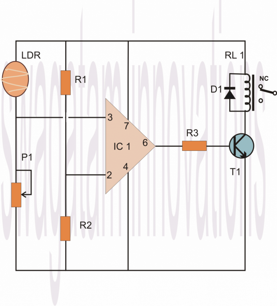
We can see that the Pin #7 of the opamp which is the +supply pin is connected to the positive rail, similarly its pin #4 which is the negative supply pin is connected to the negative or rather the zero supply rail of the power supply.
The above couple of pin connections powers the IC so that it can carry on with its intended functions.
Now as discussed earlier, pin #2 of the IC is connected at the junction of two resistors whose ends are connected to the power supply positive and negative rails.
This arrangement of the resistors is called a potential divider, meaning the potential or the voltage level at the junction of these resistors will be approximately the half of the supply voltage, so if the supply voltage is 12, the junction of the potential divider network will be 6 volts and so on.
If the supply voltage is well regulated, the above voltage level will also be well fixed and therefore can be used as the reference voltage for the pin #2.
Therefore referring to the junction voltage of the resistors R1/R2, this voltage becomes the reference voltage at pin #2 which means the IC will monitor and respond to any voltage that might go above this level.
The sensing voltage which is to be monitored is applied to pin #3 of the IC, in our example it is via an LDR. The pin #3 is connected at the junction of the LDR pin and a preset terminal.
That means this junction again becomes a potential divider, whose voltage level this time is not fixed because the LDR value cannot be fixed and will vary with the ambient light conditions.
Now suppose you want the circuit to sense the LDR value at some point just around when dusk falls, you adjust the preset such that the voltage at pin #3 or at the junction of the LDR and the preset just crosses above the 6V mark.
When this happens the value rises above the fixed reference at pin #2, this informs the IC about the sense voltage rising above the reference voltage at pin #2, this instantly reverts the output of the IC which changes to positive from its initial zero voltage position.
The above change in the state of the IC from zero to positive, triggers the relay driver stage which switches ON the load or the lights which might be connected to the relevant contacts of the relay.
Remember, the values of the resistors connected to pin #2 may also be altered for altering the sensing threshold of pin #3, so they are all inter-depended, giving you a wide angle of variation of the circuit parameters.
Another feature of the R1 and R2 is that it avoids the need of using a dual polarity power supply making the involved configuration very simple and neat.
Interchanging the Sensing Parameter with Adjustment Parameter
As shown below, the above explained operation response can be just reversed by interchanging the input pin positions of the IC or, by considering another option where we only inter-change the positions of the LDR and the preset.

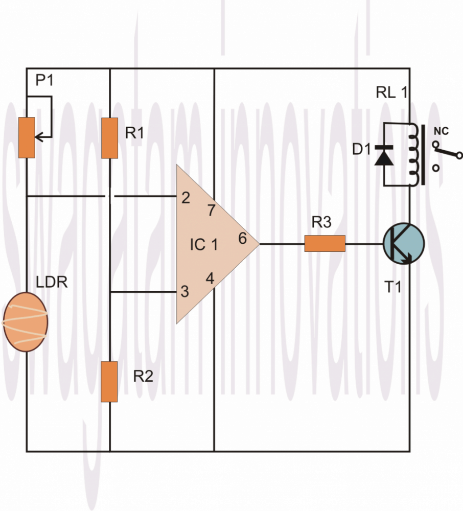
THis is how any basic opamp behaves when it is configured as a comparator.
To summarize we can say that in any opamp based compartaor, the following operations take place:
Practical Example#1
1) When the inverting pin (-) is applied a fixed voltage reference, and the non-inverting (+) input pin is subjected to an altering sensing volatge, the output of the opamp remains 0V or negative as long as the (+) pin voltage stays below the (-) refernce pin voltage level.
Alternately as soon as the (+) pin volatge goes higher than the (-) voltage, the output quickly turns positive supply DC level.
Example#2
1) Conversely, when the non-inverting pin (+) is applied a fixed voltage reference, and the inverting (-) input pin is subjected to an altering sensing voltage, the output of the opamp remains supply DC level or positive as long as the (-) pin voltage stays below the (+) refernce pin voltage level.
Alternately as soon as the (-) pin voltage goes higher than the (+) voltage, the output quickly turns negative or switches OFF to 0V.
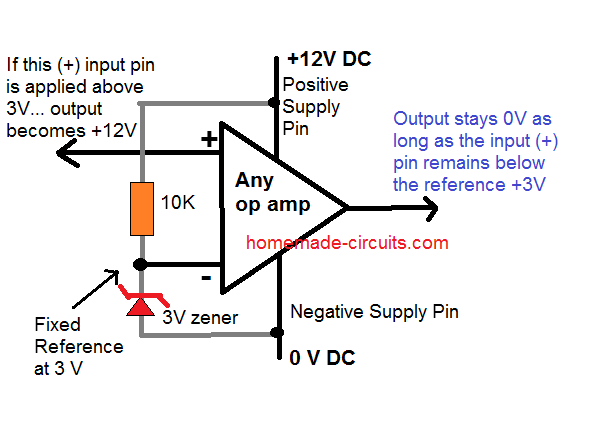
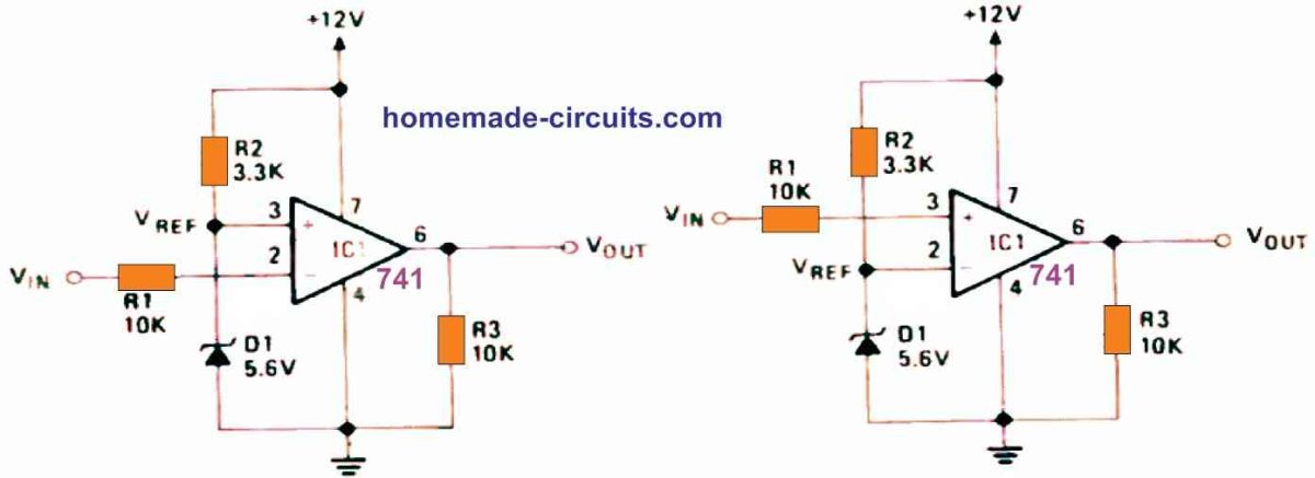
Basic Comparator Working
The circuit in the below figure operates in a relatively straightforward manner: The combination of R2 and Zener diode D1 produces a fixed reference voltage (VREF). It is applied straight to the op-non-inverting amp's input terminal, pin 3. Via the current limiting resistor R1, the input or test voltage VIN is connected to the inverting input terminal (pin 2). When VIN is less than VREF, the op amp output is high (to positive saturation), but when VIN is greater than VREF, the output is low (to negative saturation).
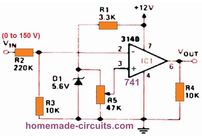
Op amp Comparator with High Voltage Input
As shown in the below figure, using a VOLTAGE DIVIDER, we can utilize a voltage comparator to provide high-value, variable voltage triggering. There is no regenerative switching in this circuit.
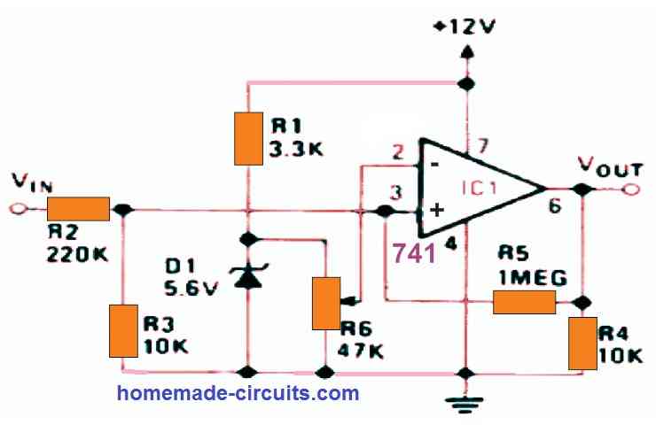
Op Amp Comparator with High Value Input, Regenerative Switching
The next circuit, like the previous one, provides high-value, variable-voltage input switching (0 to 150 V). It has regenerative switching capabilities.
Op Amp Comparator as Over Current Indicator
When the load current reaches a value defined by R6, the output turns high to indicate an over current situation. By inverting the connections to IC1's pins 2 and 3, the output will go low to indicate an over-current situation.
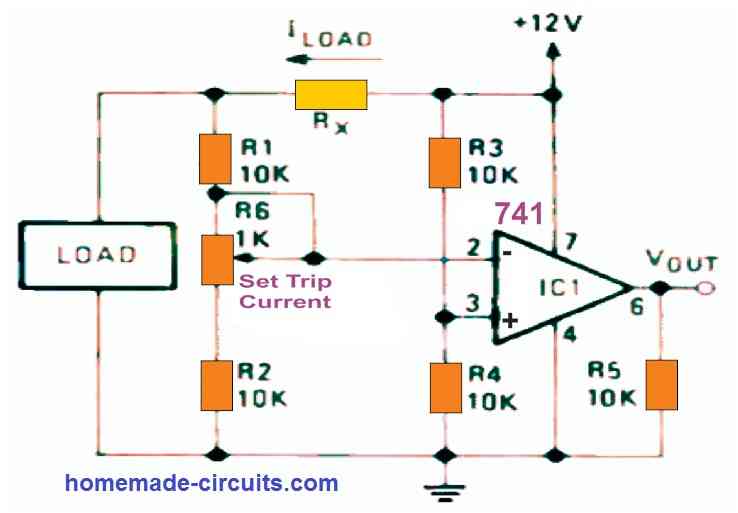
The diagram below demonstrates how a comparator circuit may be configured to operate as an over-current switch, producing a high output when the load current exceeds a given value - which you can set using potentiometer R6. Current sensing resistor RX is set such that it drops around 100 millivolts at the appropriate trip point. As a result, a fixed reference voltage equal to 1/2 the supply voltage is provided to pin 3 of the op amp through the voltage divider comprised of R3 and R4. Pin 2 receives a similar but current-dependent voltage through Rx, R1, R6, and R2.
In fact, the two sets of components form a Wheatstone bridge, with one side supplying pin 3 and the other supplying pin 2, and the op-amp serving as a bridge-balance detector. As a result, the circuit's trip points are unaffected by fluctuations in supply voltage but are very sensitive to changes in load current.

Comments
I build various of your circuits and all works 100% and was what i need, so thanks a lot. I want to build above to put between my solar batteries and an extra battery for charge purposes. My system is 12v , but the volts go up to 13,6. If I put the same value resistor on both 2 and 3 and power from the solar batteries and extra battery will this then work till voltage is equal.
Regards
Hi Swagatam,
I am interested in finding a circuit design for my solar tracker.
I’m using a small pv panel as my voltage source. It’s output is 11 to 15 volts dc.
The motor to rotate the tracker is a small 12v geared motor with 5 rpm output shaft. The motor shaft turns an all thread rod, which pulls the movable deck of the tracker around about a center pin.
I would like to use two LDR’s to sense when the tracker is properly aligned with the sun and shut the motor off at that point. As the sun moves the circuit will turn on the motor again so that the tracker will follow the sun.
The tracker will only move in one direction and I will reset it manually after about 2 hours of use. It’s for a solar cooker.
The motor only needs to turn one direction, and it needs a controller with the light sensing ability to shut off the motor when the light is equal on both LDR’s.
I am hoping you might know of a circuit design that would accomplish this task.
Thank you very much.
David
Hi David, I think I already have this circuit in my website. Please check out the following article, and let me know if you have further doubts:
https://www.homemade-circuits.com/how-to-build-dual-solar-tracker-system/
What should be the minimum difference value for inv and non inv. Thanks.
for what? what are you trying to accomplish?
To calculate the appropriate resistor for battery monitor using lm324
OK but that’s not the right way, because the cut-off difference can vary from opamp to opamp. Instead you can randomly select a fixed reference much lower than the supply voltage and then adjust the preset to create a cut off just above or under this reference voltage. Later this preset could be removed by replacing it with an appropriately matched fixed resistor.
Hi, i am Amarnath i want know that how op amp is working on single polarity supply instead of using dual polarity supply making +ve and -ve of dual polarity supply connected to ground
Amarnath, the circuit is actually working with a dual supply…the potential at pin#2 is divided by 50% of the supply to create the required +/- supplies, with reference to the power supply (-) which now acts like the ground.
hi..
If I am having a certain power on one hand and we have to compare it with a variable power. Is there is a possible way.
you can try the concept explained in the above article.
Hi Swagatam, I am trying to make a kind of comparator cum voltage level detection circuit. Basically there are two main components to it. First is the strain gauge which gives either NEGATIVE voltage or POSITIVE voltage – only one is present at a time. Now whenever this voltage is present I require an output of 5 VDC from the circuit. This 5volts should be triggered when the input voltage is either 2.5 V and above or -2.5V and above i.e. upto -5 volts. I want to use dual rail 12 volt supply as it is available with my system. Kindly suggest me a circuit design.
the bridge will enable you to get a +12V regardless of the input polarity condition, whether it's negative or positive, in other words it will convert the toggling +/- outputs of the opamps to always a (+) voltage
Thanks for the above clarification. Another query was that you mentioned "The outputs of the two opamps may then be connected to the input of a bridge rectifier". What is the use of the bridge rectifier, as the outputs would be DC if i am not wrong. Kindly help.
will do but the output will be 12V then,
a 7805 may be used after the bridge for obtaining the required 5V
Is is possible to use the above using +12 & -12 supply ?
…….The R1/R2 should be referenced to ground and not to (-) of the supply
Hi Janesh, you can do it by using two 741 IC opamp configured as comparators, as shown in the above diagrams, but the supply will need to be dual not single. It should be dual 5V supply since the required output is 5V
So the supply (+)5v and (-)5v go across the R1/R2 and the pin7/4 rails.
The outputs of the two opamps may then be connected to the input of a bridge rectifier…the output from the bridge will generate the intended 5V for the specified conditioned.
one of the opamps will have its pin3 clamped with +/- via rail via R1/R2 while the other with its pin2.
The free ends of the relevant opamp inputs could be configured with the strain gauges.
The +/- 5V supply can be created with the help of 7805/7905 complimentary pair ICs
Hi,thanx a lot for your projects .How do I go about constructing a minute circuit which senses light and create an alarm if the light gets below a particular set value?
Hi, thanks, you can try the last circuit shown in the folowing article:
https://www.homemade-circuits.com/2012/01/how-to-make-light-activated-day-night.html
You can replace the relay with a small buzzer for getting the required alarm.
good evening…the image is not opening.