In this article I have explained, how to send and receive SMS using GSM modem which is controlled by Arduino. Let us see, what GSM modem is, how to interface it with Arduino, how to send SMS with the setup.
We are also going to explore what are all applications we can achieve with GSM modem other than sending text message by a human.
What is GSM modem?
GSM stands for Global System for Mobile communications; it is a standard which was developed by ETSI (European Telecommunications Standard Institute) who described the protocols for 2G communication.
It is the first digital protocol for mobile communication which is optimized for full duplex voice communication. In a nutshell full duplex communication means both the parties can send/receive data (or voice) simultaneously.
The GSM protocol also allows transfer of packet data, such as GPRS and EDGE.
SIM800 GSM modem:
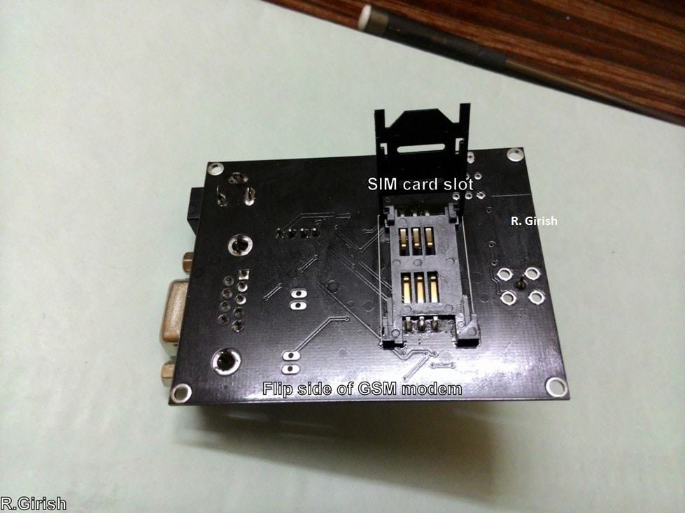
GSM modem is a hardware which accepts a valid SIM card (Subscriber Identity Module), basically any SIM will work, which supports GSM protocol and with a network subscription.
It is like a mobile phone without Screen and keypad. It has four I/O pins depending on the model you choose.
Two for TX and RX (transmit and receive), another two pins for VCC and GND, which is common in all.
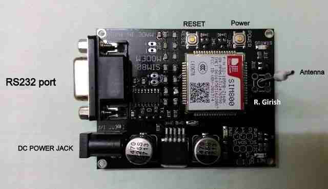
It also consist of RS232 port for serial communication between the modem and computer, however we are not going to use in this project.
It has standard DC power jack, which can be powered from external power sources such as voltage adapters.
It has working voltage ranging from 5 to 12V on DC jack, depending on the model. It has 3 LED indicators, for power, status, and network.
The power LED indicates the presence of power, status LED indicates whether the GSM modem is operating or not, the Network LED indicates the establishment of mobile network.
Initially network LED blinks every one second while searching for network, once it establishes the mobile network it blinks every 3 seconds.
You need to press power button for 2 to 3 seconds for activating the GSM modem, once you done, it latch to the mobile network.
To verify that your GSM modem works, just call the number of which you have inserted the SIM card. You should get ring back tone. If it does, then your module is working fine.
We are going to use SIM800 GSM modem which supports quad-band 850/900/1800/1900 MHz. if you own a SIM900 modem, need not to worry, the program and circuit is compatible in this project.
Now, you would have gained some idea about GSM modem, now let’s learn how to interface it with arduino.
Circuit Diagram:
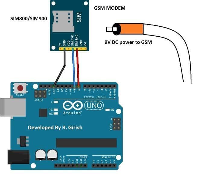
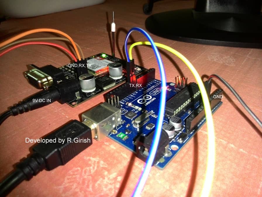
As you can infer form the diagram, the circuit connection is dead easy. You just need 3 male to female header pins. A USB cable is mandatory in this project, as we are going to communicate via serial monitor.
Always, power the GSM modem with external adaptor. The power from arduino is insufficient for the GSM modem; it could even overload the voltage regulator of the arduino.
That’s all about hardware part. Now, let’s move to coding.
Program:
//------------- Program developed by R.Girish ---------------//
#include <SoftwareSerial.h>
// GSM module connections
#define rxPin 9 // GSM TX ---> Arduino pin 9
#define txPin 8 // GSM RX ---> Arduino pin 8
// Create software serial object for GSM
SoftwareSerial mySerial(rxPin, txPin);
// Buffer to store characters typed in Serial Monitor
char text[150];
// String to store the full message
String message = "";
// Index variable for text buffer
int x;
void setup()
{
// Start hardware serial for PC communication
Serial.begin(9600);
while (!Serial) {} // Wait for Serial Monitor to open (USB boards)
// Start GSM serial communication
mySerial.begin(9600);
delay(1000); // Allow GSM module to initialize
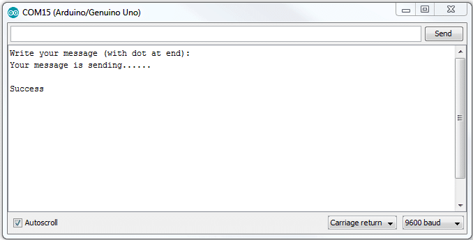
Serial.println("Write your message (with dot at end):");
}
void loop()
{
x = 0; // Reset buffer index
// Check if data is coming from Serial Monitor
while (Serial.available() > 0)
{
text[x] = Serial.read(); // Read one character
message += text[x]; // Append to message string
x++;
// Safety check to avoid buffer overflow
if (x >= 149)
{
Serial.println("Message too long!");
message = "";
x = 0;
break;
}
// ASCII value 46 = '.'
// Dot is used as END OF MESSAGE indicator
if (text[x - 1] == 46)
{
Serial.println("Your message is sending......");
SendTextMessage(); // Send SMS
ShowSerialData(); // Read GSM response
delay(1000);
Serial.println("r"); // As per original code
Serial.println("Success");
// Clear message for next SMS
message = "";
x = 0;
}
}
}
// Function to send SMS through GSM module
void SendTextMessage()
{
// Set GSM module to TEXT mode
mySerial.print("AT+CMGF=1\r");
delay(1000);
// Set destination mobile number
// Replace xxxxxxxxxx with your 10-digit mobile number
mySerial.print("AT+CMGS=\"+91xxxxxxxxxx\"\r");
delay(1000);
// Send the actual message content
mySerial.println(message);
// End message with CTRL+Z (ASCII 26)
mySerial.print("\r");
delay(1000);
mySerial.write(26);
mySerial.println(); // Extra newline (kept same as original logic)
}
// Function to display GSM responses on Serial Monitor
void ShowSerialData()
{
// Read all available data from GSM module
while (mySerial.available() != 0)
{
Serial.write(mySerial.read());
}
}
//------------- Program developed by R.Girish ---------------//
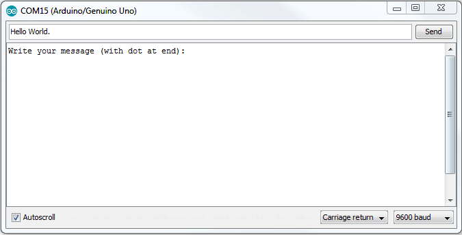
Don’t forget the dot (.) at every end of the message, otherwise it won’t sent the message to prescribed number in the program. Replace x with your 10 digital phone number in the program. Make sure you have a working SMS plan on your SIM card.
If you are not from India, please change the country code in the program.
For example:
For UK: +44
For US: +1
For Canada: +1
For Russia: +7
You can also automate the message which is sent by GSM modem by coding Arduino appropriately. You can receive automated message alerts on your phone such as: anti-theft alert, fire alarm alert, weather alert on your local area etc.
You can even connect to internet with GPRS in GSM modem, but it is subject of another article.
In one of the forth coming articles I have explained How to Receive SMS Using GSM Modem and Arduino
If you have further questions regarding how to send SMS using GSM Modem , feel free to ask in the comment section.
How to Receive SMS Using GSM Modem
In the above discussion I have explained how to send a text message using GSM modem and also discussed the basics the GSM modem.
In this section I will elucidate regarding how to receive SMS via serial monitor of the arduino IDE. We are not only going to receive SMS but, also send text message by pressing different keys. For an instant, pressing “s” will send pre-enter text message, pressing “r” will receive real time SMS.
Here is author’s prototype:
How it Works
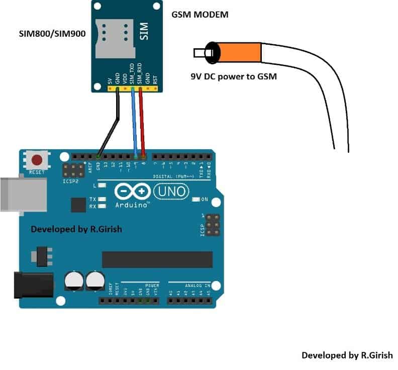
The circuit for receiving SMS using a GSM moden is very simple, you just need 3 male to female header pins. The TX of GSM modem is connected to pin #9 of arduino and RX of GSM modem is connected to pin #8 of arduino and the ground to ground connection is also given between GSM and arduino.
Always use external power supply for GSM modem, don’t connect 5Vcc from arduino to GSM modem, as there is good chance of overloading the voltage regulator of arduino.
Don’t forget to implement SMS rate cutter or something similar on your SMS subscription for reduction on your SMS expenses.
Otherwise you will end up empty account balance after sending several SMS, since there won’t be any acknowledgement from your cellular provider after every sent SMS, as the SIM card is in the GSM modem.
The only acknowledgement you get is warning SMS, regarding your empty account, so be cautious about you expenses. Now let’s move to coding part this project.
Program:
//----------------- Program developed by R. Girish -----------------//

#include <SoftwareSerial.h>

// SoftwareSerial object for GSM module
// Pin 9  -> Arduino RX  (connect to GSM TX)
// Pin 8  -> Arduino TX  (connect to GSM RX)
SoftwareSerial gsm(9, 8);

void setup()
{
  // Initialize GSM module communication
  gsm.begin(9600);           // GSM module baud rate

  // Initialize Serial Monitor communication
  Serial.begin(9600);        // Arduino Serial Monitor baud rate

  delay(100);                // Small delay for system stabilization
}

void loop()
{
  // Check if any data is available from Serial Monitor
  if (Serial.available() > 0)
  {
    // Read the incoming character from Serial Monitor
    char cmd = Serial.read();

    // Decide action based on received character
    switch (cmd)
    {
      case 's':              // Send SMS (lowercase)
      case 'S':              // Send SMS (uppercase)
        Send();
        break;

      case 'r':              // Receive SMS (lowercase)
      case 'R':              // Receive SMS (uppercase)
        Recieve();
        break;
    }
  }

  // Check if GSM module has sent any data
  if (gsm.available() > 0)
  {
    // Forward GSM data to Serial Monitor
    Serial.write(gsm.read());
  }
}

//------------------------- Send SMS Function -----------------------//
void Send()
{
  // Set GSM module to SMS text mode
  gsm.println("AT+CMGF=1");
  delay(1000);

  // Set recipient mobile number
  // IMPORTANT: Replace xxxxxxxxxx with the actual mobile number
  // Format must be exactly as shown
  gsm.println("AT+CMGS=\"+91xxxxxxxxxx\"");
  delay(1000);

  // SMS content
  gsm.println("Hello I am GSM modem!!!");
  delay(100);

  // CTRL+Z (ASCII 26) tells GSM module to send the SMS
  gsm.println((char)26);
  delay(1000);
}

//---------------------- Receive SMS Function -----------------------//
void Recieve()
{
  // Configure GSM module to immediately forward incoming SMS to serial
  gsm.println("AT+CNMI=2,2,0,0,0");
  delay(1000);
}

//----------------- Program developed by R. Girish -----------------//
Entering the Phone Numbers
Enter the recipient phone number on “xxxxxxxxxxx” in the program with your country code at the beginning.
Enter the text that you want to send in the program within the quotation mark: gsm.println("Hello I am GSM modem!!!"); // The SMS text you want to send
Compile the program and upload to arduino.
Insert the SIM card and power the GSM modem with external power supply and press the power button for 3 seconds (depending the model), wait for 10 to 20 seconds to establish mobile network, the network LED should blink once in every 3 seconds. If everything is stated above is done, we are ready to go for next step.
Now open serial monitor and press “r” the GSM modem is ready to receive SMS. Now send a text message from any mobile phone to number of the SIM which is inserted on GSM modem.
The text message should pop up on the serial monitor, something similar to illustrated below:

The “Hello world” is the message sent to GSM modem and the number from which the text message is sent also displayed.
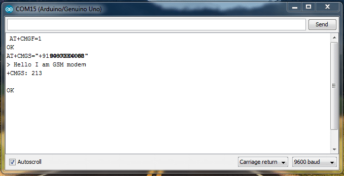
Now, let send SMS to the pre-entered number in the program with pre-entered message. Press “s” and you will see something similar illustrated below: The sent SMS is “Hello I am GSM modem”.
Now, you know how to send and how to receive SMS using GSM modem.


Comments
Is it possible to route all incoming SMS messages to my Telegram bot? I would like a tutorial on this. Or perhaps forwarding all received SMS messages that are inside the Arduino SIM slot to a single designated SMS number on my physical phone.
Yes, forwarding all received SMS messages is possible. The Arduino can read every incoming SMS from the GSM module and immediately resend it to another phone number using the AT+CMGS command. Sending the SMS to a Telegram bot is also possible but it requires using the GSM module’s GPRS internet connection and calling the Telegram Bot API, which is more complex.
I have never done anything with Arduino before. But would like to do something like this, so that if an alarm is activated at our small school, it will automatically text to a dozen numbers “Emergency at school.” Maybe repeat three times.
Could you help me with how to change the code to add more numbers?
Can I use any Arduino?
Can I use any GSM 800?
Or is there a specific one that is better?
sure, I will try my best to help you for this project, but I cannot guarantee its working because it is difficult for me to test and confirm it practically.
I recommend only Arduino UNO for this project, and no other variant.
Yes, you can use any GSM 800 but SIM800L or SIM800A are the most commonly used modules. SIM900 also works but is slightly older. Ensure that your module supports your countrys mobile network frequencies.
You can modify the existing receiver code in the following manner, for fulfilling your desired specifications:
#include
SoftwareSerial gsm(9,8);
String phoneNumbers[] = {
“+911234567890”, // Replace with actual numbers
“+919876543210”,
“+911122334455”
}; // Add more numbers if needed
void setup() {
gsm.begin(9600); // Setting the baud rate of GSM Module
Serial.begin(9600); // Setting the baud rate of Serial Monitor (Arduino)
delay(100);
}
void loop() {
if (Serial.available() > 0) {
switch(Serial.read()) {
case ‘s’:
case ‘S’:
sendEmergencySMS();
break;
case ‘r’:
case ‘R’:
Recieve();
break;
}
}
if (gsm.available() > 0) {
Serial.write(gsm.read());
}
// Example alarm condition: If a digital input pin goes HIGH, trigger SMS
if (digitalRead(7) == HIGH) { // Change 7 to the actual alarm pin
sendEmergencySMS(); // Send SMS when alarm is triggered
delay(60000); // Wait 1 minute before checking again to avoid spam
}
}
void sendEmergencySMS() {
for (int i = 0; i < sizeof(phoneNumbers) / sizeof(phoneNumbers[0]); i++) { gsm.println("AT+CMGF=1"); // Set SMS mode delay(1000); gsm.print("AT+CMGS=\""); gsm.print(phoneNumbers[i]); gsm.println("\""); delay(1000); gsm.println("Emergency at school!"); // Message content delay(100); gsm.write(26); // ASCII code of CTRL+Z to send the message delay(5000); // Wait before sending to next number } }void Recieve() { gsm.println("AT+CNMI=2,2,0,0,0"); // AT Command to receive a live SMS delay(1000); }
Thanks for your comments. I will give it a try.
No problem..
hello sir,
i am not getting the reply from gsm module..can you lease help to how to get the reply..and there was a error showing in the program at in this line
mySerial.print(“AT+CMGS=”+91xxxxxxxxxx”r”);
if we given like shown below its not showing any error
mySerial.print(“AT+CMGS=\”+91xxxxxxxxxx\”\r”);