In this post I have explained a few circuit concepts which can be employed for converting or modifying any ordinary square wave inverter to sophisticated sine wave inverter design.
Before studying the various designs I have explained in this article, it would be interesting to know the factors which typically makes a sine wave inverter more desirable than a square wave design.
How Frequency Works in Inverters
Inverters basically involve frequency or oscillations for implementing the boost and inversion actions. The frequency as we know is generation of pulses at some uniform and calculated pattern, for example a typical inverter frequency may be rated at 50Hz or 50 positive pulses per second.
The fundamental frequency waveform of an inverter is in the form of square wave pulses.
As we all know a square wave is never suitable for operating sophisticated electronic equipment such as TV, music players, computers etc.
The AC (alternating current) mains that we acquire at our domestic mains outlet also consists of pulsating current frequency, but these are in the form of sinusoidal waves or sine waves.
It's normally at 50Hz or 60Hz depending upon the particular country utility specs.
The above mentioned sine curve of our home AC waveform refers to the exponentially rising voltage peaks which constitute the 50 cycles of the frequency.
Since our domestic AC is generated through magnetic turbines, the wave form is inherently a sine wave, so doesn't require any processing further and becomes directly usable in homes for all types of appliances.
Conversely in inverters, the fundamental waveform are in the shape of square waves which needs thorough processing in order to make the unit compatible with all types of equipment.
Difference between Square Wave and Sine Wave
As shown in the figure, a square wave and sine wave may have identical peak voltage levels but the RMS value or the root mean square value may not be identical. This aspect is what that makes a square wave particularly different from a sine wave even though the peak value may be the same.
Therefore a square wave inverter working with 12V DC would generate an output equivalent to say 330V just like a sine wave inverter operating with the same battery but if you measure the output RMS of both the inverters, it would differ significantly (330V and 220V).
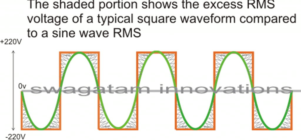
The image incorrectly shows 220V as the peak, actually it should be 330V
In the above diagram, the green colored waveform is the sine waveform, while the orange depicts the square waveform. The shaded portion is the excess RMS which needs to be leveled of in order to make both the RMS values as close as possible.
Converting a square wave inverter into a sine wave equivalent thus basically means allowing the square wave inverer to produce the required peak value of say 330V yet having an RMS just about equal to its sine wave counterpart.
How to Convert/Modify a Square Waveform to Sine Waveform Equivalent
This can be done either by carving a square wave sample into a sine wave form, or simply by chopping a sample square waveform into well calculated smaller pieces such that its RMS becomes very close to a standard mains AC RMS value.
For carving a square wave to a perfect sine wave, we can employ a wien bridge oscillator or more precisely a "bubba oscillator" and feed it to a sine wave processor stage. This method would be too complex and is therefore not a recommended idea for implementing an existing square wave inverter to a sine wave inverter.
The more feasible idea would be to chop the associated square wave at the base of the output devices to the required RMS degree.
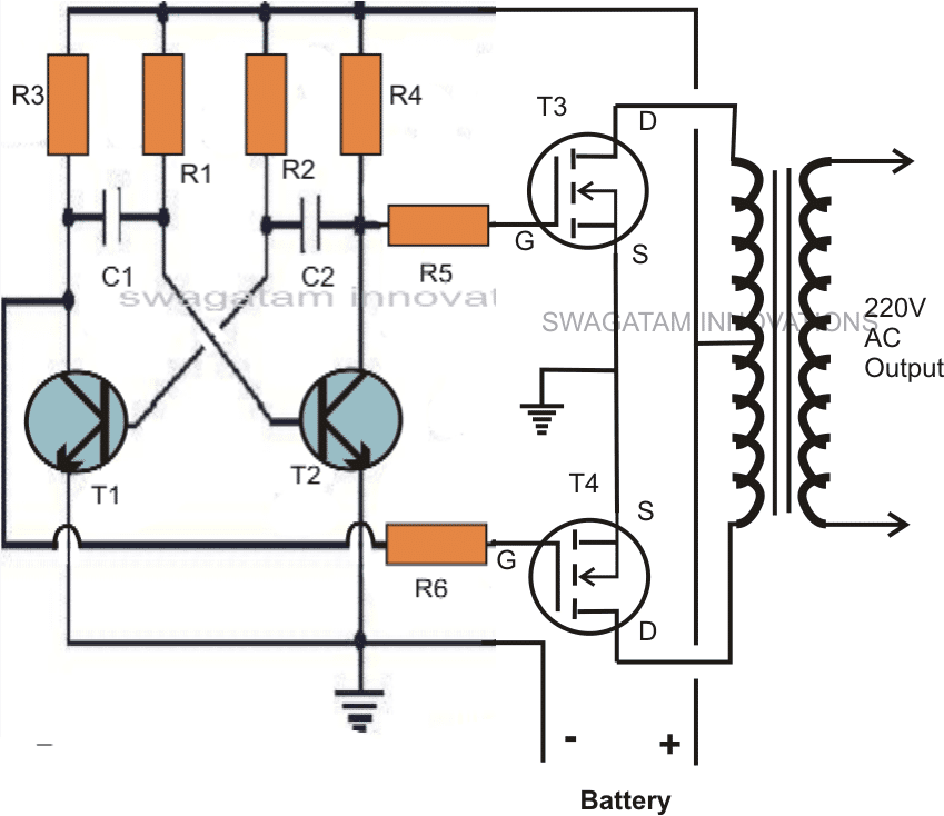
One classic example is shown below:
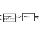
The first diagram shows an square wave inverter circuit. By adding a simple AMV chopper we can break down the pulses at the base of the relevant mosfets to the required degree.
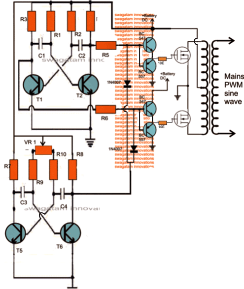
Modified square wave to sine wave equivalent inverter version of the above circuit.
Here the lower AMV generate pulses at high frequency whose mark/space ratio can be suitably altered with the help of preset VR1. This PWM controlled output is applied to the gates of the mosfets in order to tailor their conduction into the stipulated RMS value.
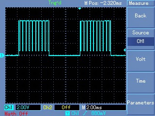
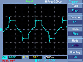
Expected typical waveform pattern from the above modification:
Waveform at the mosfet gates:
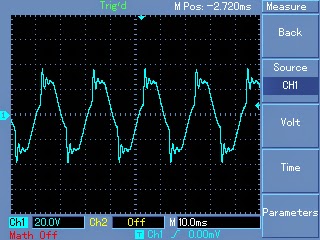
Waveform at the output of transformer:
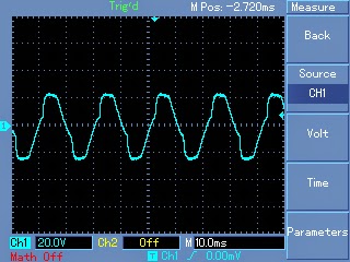
Waveform after proper filtration using inductors and capacitors at the output of the transformer:
Parts List
R1, R2, = 27K,
R3, R4, R5, R6, R7,R8, R9, R10 = 1K Ohms,
C1,C2 = 0.47uF/100V metallized
C3, C4 = 0.1uF
T1, T2, T5, T6 = BC547,
T3, T4 = any 30V, 10amp mosfet, N-channel.
D1, D2 = 1N4148
VR1 = 47K preset
Transformer = 9-0-9V, 8 amp (specifications must be selected as per the output load for correct powre optimization)
Battery = 12V,10AH
Getting Better Efficiency Rate
The above explained conversion or modification will provide around 70% of efficiency with the achieved RMS matching. If you are interested in getting better and precise matching then probably a an IC 556 PWM waveform processor would be required.
You would want to refer to this article which shows the principle behind modifying a square waveform into a sine waveform using a couple of IC555.
The output from the above mentioned circuit can be similarly fed to the gate or the base of the relevant power devices which are present in the existing square inverter unit.
A more comprehensive approach may be witnessed in the this article where an IC 556 is used for extracting precise PWM based modified sine wave equivalents from a square wave sample source.
This waveform is integrated with the existing output devices for implementing the intended modifications.
The above examples teach us the simpler methods through which any existing ordinary square wave inverter may be modified into a sine wave inverter designs.
Converting into an SPWM
In the above article I have explained how the waveform of a square wave inverter could be optimized for getting a sine wave kind of waveform by chopping the square wave into smaller sections.
However a deeper analysis shows that unless the chopped waveform is not dimensioned in the form of SPWMs, achieving a proper sinewave equivalent may not be possible.
To satisfy this condition an SPWM converter circuit becomes essential for carving out the most ideal sinewaveform from the inverter.
The basic idea is to chop the output power devices with sine wave pulse width modulation, so that the power devices force the transformer winding to also oscillate in the SPWM mode and ultimately generate an optimized pure sine wave at the secondary side. The magnetic induction of the pulsed SPWM across the transformer winding finally gets the shape of a pure sine wave due to the inductive filtration of the transformer winding.
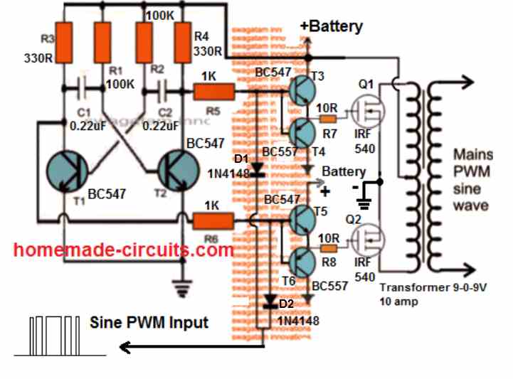
The following diagram shows how this could be effectively implemented with the concept discussed above.
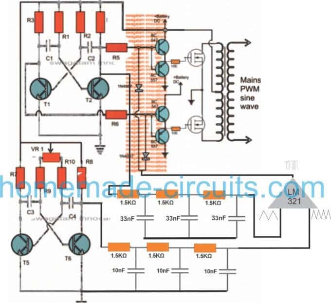
Through one of my earlier articles we understood how an opamp could be used for creating SPWMs, the same theory could be seen applied in the above concept. Two triangle wave generators are used here, one accepting the fast square wave from the lower astable, while the other accepting slow square waves from the upper astable and processing them into corresponding fast and slow triangle wave outputs, respectively.
These processed triangle wave are fed across the two inputs of an opamp, which finally converts them into SPWMs or sine wave pulse widths.
These SPWMs are used for chopping the signals at the gate of the mosfets which ultimately switch the waveform over the connected transformer winding for creating an exact replica of a pure sine waveform at the secondary side of the transformer through magnetic induction.
How to Calculate the Part Values
Astable Multivibrator Frequency (Square Waves):
Formula: f = 1 / (0.693 * (R1 + 2 * R2) * C)
For the fast square wave generator:
Let R1 = 10k ohms, R2 = 100k ohms, C = 10nF (example values).
ffast = 1 / (0.693 * (10000 + 2 * 100000) * 10e-9)
ffast = 1 / (0.693 * 210000 * 10e-9)
ffast = 68 Hz
For the slow square wave generator:
Let R1 = 10k ohms, R2 = 1M ohm, C = 100nF (example values).
fslow = 1 / (0.693 * (10000 + 2 * 1000000) * 100e-9)
fslow = 1 / (0.693 * 2010000 * 100e-9)
fslow = 7.1 Hz
RC Integrator Cutoff Frequency (Triangle Wave Generators):
Formula: fc = 1 / (2 * π * R * C)
For each RC stage assume R = 1.5k ohms and C = 33nF.
fcstage = 1 / (2 * 3.1416 * 1500 * 33e-9)
fcstage = 1 / (2 * 3.1416 * 0.0000495)
fcstage = 3223 Hz
For three stages the overall response rolls off steeply approximately at the same fcstage.
Op-Amp SPWM Generation:
The op-amp compares the fast triangle wave (carrier) and the slow triangle wave (modulating signal). The output is high when the carrier is greater than the modulating signal. This generates a sinusoidal PWM (SPWM).
Gate Drive Requirements for MOSFETs:
Formula: Ig = VSPWM / Rg
Assume VSPWM = 10V and Rg = 1.5k ohms.
Ig = 10 / 1500
Ig = 0.0067 A (6.7 mA)
This ensures the MOSFET switches efficiently.


Wat is het nullast vermogen.
Hello sir, why does the inverter have a vibrating/humming sound when inductive load is added to it
Hi Hillary, Inductive loads typically create magnetic fields when they work. These magnetic fields can affect the parts inside the inverter which can make them vibrate. This vibration usually matches the frequency of the inverter’s frequency which is usually 50 Hz or 60 Hz and that’s why you might hear a humming noise.
Does this mean that even a sine wave inverter will hum when an inductive load is connected to it?
If yes, is there a way to reduce the humming sound?
A proper sine waveform will generate minimum or negligible humming sound. You can reduce it by using a pure sine waveform and by clamping the transformer tightly with the body of the inverter.
Sir thanks for spwm circuit above, can the circuit power LED TV
Hi Samuel, yes it can be used to power LED TV, but only after correctly dimensioning the SPWM RMS value and after proper filtration.
Hello Mr. swagatam, did you use any programm on any of the ic including the 556?
Hello Sadiq, No programming were used, these ICs do not need any kind of programming. By the way I cannot see any ICs in the above concepts.
Hello good afternoon, my name is Jean Carlos. Regarding the issue of the inverter, I would like to ask about its usefulness. There will be videos of its assembly and production in refrigerators or televisions.
Hello Jean,
Sine wave and modified sine wave inverters can be very useful for driving refrigerators and TVs
Hello sir can u help me with a circuit that will completely chop off the excessive RMS of a square wave inverter, converting it to pure sine wave.
Hi Atuh, You will have to implement the following concept an feed the SPWM across the mosfet gates for the chopping:
https://www.homemade-circuits.com/how-to-generate-sinewave-pwm/
Mr. Swagatam I’ve brought a 12v 650va ups Which is pwm square wave. Around how many amps do you think it will be drawing from the battery at no load though it will be more than a ferrite core transformer. Please tell me if it will draw much current.
Before I start using it. If it will draw a lot of current on no load i will return it back.
Hello Sadiq, It can be difficult to judge how much current your inverter will consume without load. You may have to check this by connecting an ammeter in series with the battery positive line.
What is the wave firm after modifying the square wave using spwm comparator
Thanks swagatam but what about a fully loaded 100w modified sinewave inverter with a ferrite core transformer how much current will it draw max.
It will draw approximately 90 watts. You can divide this 90 watt with the battery voltage to get the approximate current value.
Hello Mr swagatam how many amps does an almost fully loaded 75w inverter draws. And it’s efficiency at half load.
Hello Sadiq, a 12V 75 watt inverter with a center tap iron core transformer would draw around 6 amp current at around 70% efficiency. The efficiency would remain almost the same even at half load.
Ok what about at higher efficiency such as 85 percent?
For higher efficiency you may have to opt for a full bridge topology with torroidal type of transformer, or ferrite based transformer
I’m using a 75w rated 12v dc inverter with a ferrite core transformer. Due to electricity problems I had to use an inverter and i just want a small inverter which should draw at least maximum of 7 to 8amp of current. Load are ceiling fan rated 68w two led bulbs rated 5w and mobile charger charging my phone. Should I buy a 100w or an 80w inverter in order to draw between 6 to 8 amperes?
You will have to buy at least a 100 watt inverter for optimal performance.
How many ampere do you think the 100w inverter with ferrite core transformer will draw at full load
It will depend on the efficiency of the inverter, and the load current.
Ok that is at high such as 80 percent
Divide 100 with 12V that will give you the maximum current the inverter will consume at full load.
OK problem almost solved because I have brought the iPhone battery pack whose battery was rated 1,450Mah in series which made it different from other battery packs but I wanted it to fully charge my iPhone more than one time. Can I increase it’s lasting by changing both the batteries to 3,000Mah in series which was 7.62v into 7.62v 3,000Mah?
Yes, you can add the batteries in series to make it last longer.
For further questions you can discuss under the following article:
Wireless Battery Charger Circuit
OK I changed the coils into a bigger enamelled copper coil but doesn’t charged my phone unless I bring it too close at that point that’s when it charges at extreme high current is it because of the enamelled copper coil that stop’s it from charging the phone when I close the power bank
It’s not because of enameled copper wire, it’s because of the air resistance which prevents the transfer of current as distance is increased.
OK but the input supply current I.e the battery yto PCB wires?
Sorry, I did not understand your question.
Hello I couldn’t because the wires are so tiny but the turns are many but I think it’s more than 25 turns. Also the inverter (1500va) was able to handle the load (150watt) I think I should just connect the inductors in parallel.
I have a wireless power bank rated 5w max is there a way I can increase it’s charging speed to 7.5 or 15w
The wire thickness must be more than 1 mm otherwise it cannot be used at the inverter output.
You will have to open the power bank and upgrade the coil wire thickness and the input supply current to increase its capacity.
OK but when was looking for inductor I found a magnetic ballast rated 20watt when I connect it with a 1uf 400v non polar capacitor it produced a pure sinewave but cannot handle a 150watt fan because the voltage drops around 85 to 90volt from 220volt. is it because of the thin wires. Or how do I increase the ballast watts rating..
Does the inverter handle the load normally without the inductor?
How many turns does the inductor have? According to me it should not be more than 25 turns wound over an iron core. The iron core thickness can be 1 cm.
The wire thickness of the inductor should be at least 1 mm.
OK what type of inductor should I use the secondary winding of a UPS transformer. Also the capacitor should now be smaller right.
You will have to make the inductor with some trial and error. Try with a 25 turn inductor wound with a 1 mm copper wire. If it doesn’t give proper results try increasing the number of turns. Capacitor can be a 1uF/400V non polar
Mr.swagatam, if I use an inductor to reduce aharmonic in the modified sinewave ups to converted it into a pure sinewave rather than using the capacitor which one Will be more efficient.
Hello Sadiq, you will need an inductor and also a capacitor for the conversion, without a capacitor the conversion may not be possible. Using capacitor and inductor both is more efficient than using only capacitor.
Thanks. But Mr.swagatam to increase my ups I think the easiest way is to use an AC to DC adapter and I have a 12v 5A and 16v 4.5A if I connect them in series how many amp Will I get at 28v.
Sorry, I am not sure how an AC to DC adapter can be used to increase the power of an UPS. The current from your series connection should be 4.5 amps.
Hello, Mr. Swagatam how does the AC to DC adapter small transformer produce DC voltage with high current. I wanted to know how it works.
Hello Sadiq,
It works by using a high frequency ferrite core transformer.
You can read the following post for more info:
https://www.homemade-circuits.com/how-to-understand-switch-mode-power/
How can I modify my ups transformer?
Thanks. But can increase my ups charging currents please show me a diagram if there is any.
You will have to modify the UPS transformer and the charger circuit, it cannot be done externally.
Yes it turned into a puresine wave but what can be it’s efficiency.
There will be some wastage of power through the capacitor, but that can be quite small.
Hello. I think the capacitor may cause the the MOSFET to overheat but I never tried it.
I don’t think that would happen if the capacitor is connected to the transformer secondary wires.
Hello Mr.swagatam I have a 24v modified sinewave ups rated 1500va. Is there any way I can convert it to a pure sinewave ups or I should use a large capacitor to reduce the high frequency.
Hello Sadiq, you can use a large capacitor of around 3uF/400V at the secondary side of the transformer to convert modified waveform into sine waveform
Hi
i am trying to make the simpliest pure sine wave inverter with the least components-using a 555 -if i get the 555 square wave at 50hz– signal and condition it to a sine wave with a LC circuit –then use the sine wave at 50hz to fire x2 mosfets on a 12-0-12 transformer–would something like that work –how would i seperate the pos and neg portion of the sine wave to trigger each of the FETs
any ideas –
thanks
leslie
Hi, that may be possible, but for this you might need a sine wave amplifier circuit, which can be implemented using any good mosfet audio amplifier circuit. The sine wave could be applied at the input of the audio amplifier, and at the output side of the amplifier the loudspeaker could be replaced with a transformer primary. Than, the secondary of the transformer could be used to generate the amplified 220V or 120C sine wave AC.However the whole system could become quite inefficient and the mosfets could generate a lot of heat….the better alternative is to go for PWM based inverter.
wouldnt it be easier to take a piece of steel pipe and wrap it with two wraps of insulated wire to smooth out a square and make it a sign wave?
basically a transformer.
I would want somebody to try it check the response and efficiency!
wow,thanks for the reply.i usually dont even bother asking questions and expected this was a necro thread.thats top class swagatam,respect!
My pleasure Robert!
Pls what home made simple circuit can i add to my inverter to make it a sine wave strong enough to pick my electronics
there’s no simple circuit to convert square wave inverter into sine wave inverter.
Hi, which one do I use as best modified sine wave inverter in my shop? The first in the seven modified sine wave inverter or this down one in this post? Thanks
Hi, you can use the second circuit from the following link:
https://www.homemade-circuits.com/modified-sine-wave-inverter-circuit-2/
The first two circuit in your #1 modified sine wave inverter or the second using NOT gate, sir?
I am referring to this circuit:
https://www.homemade-circuits.com/wp-content/uploads/2018/08/modified-sine.jpg
Thank u sir u r my teacher, I will try ths next week. I have a ups transformer 6-0-6 with a battery 32ah. Hope am gona get 220ac output
You are welcome Morris, wish you all the best!
Yes my lecturer,Swagatam! How are you? Can I use ths circuit now with 24-0-24 or 18-0-18 transformer adding a 12v regulator to feed the oscillator? Thanks in advance!
Yes you can use the mentioned transformer with the 4017 circuit.
Swagatam. How r u? I have two 12ah lead acid battery which I want to use with this circuit u referred to me as best in my workshop. My question is that can I replace the transistors with mosfet in that Same connection? Two, is it possible using a 18-0-18 transformer with the two batteries to get 24 volts and work efficiently?
Hi Morris, yes all that you have mentioned are possible.
Just make sure to add diodes between center tap and the outer terminals of the transformer to safeguard the mosfets from damage
So if I want to use irfan44 four pieces, I jst connect them the same way the four TIP transistors are connected?
Yes that’s correct…
Adding diodes between the CENTRE tap and the outer terminals means that all positives of the diodes to point CENTRE tap wire and negative sides to be wired to the outer terminal of the transformer? Thanks
That’s right, the cathodes will go the center tap.
Yes sir, do u have any best modified sine wave inverter charger for 24v to use in my shop so that whn the main is available it charges the battery and whn the power goes off inverter picks on in the absence of the main? Pliz guide!
The second schematic from the following article is probably the bets and the easiest design you can get.
https://www.homemade-circuits.com/modified-sine-wave-inverter-circuit-2/
for converting it into an UPS, you can implement the following concept with the above circuit:
https://www.homemade-circuits.com/how-to-convert-inverter-to-ups/
Thanks sir but do u have modified sine wave inverter charger?
The sine wave has nothing to do with the charger….you can use any battery charger depending on the battery specs.
And which type of mosfet do u recommend sir for that efficient charging! Irf3205 or which one? Thanks
Yes it can be used!
Hey there. I have a high capacity usb battery bank, it’s made up of lithium iron phosphate cells, great unit for powering usb devices. However the ac output is modified sine, which I have read will damage appliances. I am in U.K. by the way. Can I use this circuit to covert to sine wave?
Hi, yes definitely you can use the above concept. However the best way to convert your modified sine wave to reasonably good sine wave is by adding a 5uF/400V capacitor across the transformer AC output.
you can also try making the following from the scratch
https://www.homemade-circuits.com/1500-watt-pwm-sinewave-inverter-circuit/
I have couple of squarewave inverters replaced with Luminous UPS. now they are redundant and kept like scrape material But I want them to convert into sqarewave OR Solar inverter.
Hello sir ,
Thank you so much,
In the above diagram,the two diodes appear to be blocking the signal from the lm321 .What do you think?.
Hello Patrick, the op amp is used for sinking current not for sourcing current….so it is the 0V switching periods which is relevant, not the positive switching!
You can modify a square wave inverter by driving the square wave oscillator with a sine wave IC oscillation driver or by modifying the output of the square wave inverter with a 105J 650V Cap to the output transformer.
Hello,
square-wave can use transistor for the output stage, modify-square-wave can also use transistor too for the output stage, how about pure sine wave? can it also use transistor for the output stage? do you have pure sine wave diagram ? thanks a lot.
Hello, it is possible but will create lot of heat on the transistor, here’s an example
https://www.homemade-circuits.com/make-this-1kva-1000-watts-pure-sine/
Pls sir what is the best frequency i can use for the lower PWM AMV stage
you can try 350 Hz
which filter can i connect to the transformer output for filtration and can i use this inverter for powering LED TVs
you can connect a 2uF/400V across the output of the transformer, you can use it with any electronic gadget after verifying the sine output on scope
Nice one, a 2uf 400V or 105J 400 – 650V
Sir swagatam,can the above spwm circuit power heavy loads like a refrigerator,tube lights and induction motors? Can I use it to construct a 5000w inverter, please advise.
Evans, I would recommend the following circuit instead:
1500 watt PWM Sinewave Inverter Circuit
use 10 to 15 MOSFETs in parallel for each channel, and use a 6000 watt transformer
Thanks very much for your response and help
Dear Swagatam,
# Question-1
I found that my 12 volt single battery UPS system using a transformer which secondary coil is 6-0-6 volt.
Then I open my 24 volt two battery UPS system and I found here using a transformer which is 12-0-12 volt secondary coil. I am confused about this matter because normally we found 12 volt inverter system using 12-0-12 volt secondary coil transformer and if it is 24 volt system then using 24-0-24 volt transformer.
# Ouestion-2:
I tried to convert my 24 volt UPS system to a 12 volt system by changing the transformer’s all coil VAC value (except primary coil) by converting with half value of existing system. But I am not able to do this because the UPS system not work, problem is the UPS system not go to backup mode when main/grid line off. It seems to me I have also change the circuit board some parts but where I change I do not know.
Good night sweet dreams.
Hello Md. Zahirul,
If the inverter is PWM controlled or a SPWM controlled, then the transformer primary value will be normally much lower than the battery voltage. But for a flat square wave design the two values can be similar.
Answering the second question can be difficult without checking the entire working specification of the design.
Thanks very much for your quick reply.
One more question is-
I want to use my computer 1000VA UPS as a my home UPS by replacing bigger battery and adding extra automatic battery charger. Normally we know that computer UPS can backup for small time like 15-20 minute. My question is here any other arrangement needed or not in circuit board for long backup? why not when I use it for my home backup it must be capable to take long backup period,
To increase back up you can add more number batteries in parallel, but the load must not increase. Also the additional batteries will need to be charged from an external charger. Any other changes will not be required.
Thanks Swagatam for your opinion.
Dear Swagatam,
How are you? After a long time come back to you.
I have been made my home UPS about 600VA. My UPS output voltage is 230 volt (280 volt transformer primary coil is connected for output voltage). Frequency is 50 Hz. But problem is when I connect load like one table fan then output voltage decrease to 200 volt. If I connect more load then decrease the output voltage more.
My UPS specification is-
1. Centre Tap Transformer(500 watt) which secondary coil is 13-0-13 & primary coil is 0-180-220-
260-280 volt
2. Using total 6 (3 pic in each channel) MOSFET which number is CS150N03
3. UPS input voltage is 12 volt DC.
Question-1
Now how can solve this problem or how can increase my UPS watt or output voltage?
Question-2
What should be the secondary coil voltage of transformer for 12 volt input system inverter/UPS?
It is 12-0-12 or 9-0-9 or 15-0-15
Question-3
Give me some high watt MOSFET number
Dear Md, the transformer voltage rating will depend on the oscillator circuit specifications…Depending on the PWM duty cycle of the oscillator, the transformer voltage rating could anywhere between 6-0-6V and 9-0-9V, but it cannot be 12-0-12V or higher with a 12V battery. If there’s no PWM involved then you can probably use a 9-0-9V transformer.
The MOSFeT number mentioned looks OK for the application.
However, the battery Ah must be at least 5 times higher than the load current.
Sir, do you know much about Fuelless Generator? To generate a steady electricity with a 12V DC motor and a permanent magnet alternator with a feedback charging system to the 12V battery.
Hi Don, Presently I do not have this circuit, if I happen to find one, will surely let you know!
Dear Swagatam,
You says “the transformer voltage rating will depend on the oscillator circuit specifications, and depending on the PWM duty cycle of the oscillator”
Please describe for understanding
Hello Md, you can get the complete explanation under the following article:
https://www.homemade-circuits.com/inverter-voltage-drop-issue-how-to-solve/
Dear Swagatam
Very very thanks to you for your quick repose.
Now I want to learn about PWM voltage
My questionnaires is:-
1. How PWM voltage works in inverter?
2. If my main transformer primary voltage is 12-0-12 then how much PWM voltage needed? 12 volt or 15 volt?
3. Can I take PWM voltage in seperate transformer instead of main transformer?
4. Can I connect seperate auto charging circuit in my home UPS? why not I don’t want to heating my main transformer by charging purpose.
Gentally waiting for your response.
Hello Md,
To learn how to match PWM with transformer rating, you can read the following article.
https://www.homemade-circuits.com/inverter-voltage-drop-issue-how-to-solve/
PWM is nothing but switching the transformer winding with a certain ON/OFF rate or duty cycle so that the output RMS is correctly set.
PWM is given to main transformer only.
You can use a separate transformer for charging without any issues
Dear Swagatam you said
“PWM is nothing but switching the transformer winding with a certain ON/OFF rate or duty cycle so that the output RMS is correctly set.” It’s ok but we know that switching the transformer winding done by the MOSFET functioning. Please describe in details.
“Can use a separate transformer for charging without any issue”. Fine, but then both the charger (Internal charging unit in UPS circuit board & external charger) will charge the battery or not?
I have seen some inverter board without PWM specification like “NATASHA” inverter board which is made in India. How this type of inverter works without PWM voltage?
What is the advantage of using PWM in an inverter?
Dear Zahirul, your questions cannot be explained in comments, you will have to learn the whole concept of MOSFET switching and PWM switching from the beginning, to grasp the whole working.
Dear Swagatam,
For winding UPS/IPS transformer which wire we have to winding first?
Thick wire (primary coil) or thin wire (secondary coil)?
Is there any differences for winding firstly or lastly between thick or thin wire.
Hi Zahirul, You will have to wind the high voltage winding first, and then apply the low voltage winding after a layer of insulation tape.
Thank you sir for the spwm description.Now if i put the upper astable at 50hz,what will be the freq of the lower astable,50hz?.How can i attach a feedback loop to the circuit.
Thanks.
Hi Patrick The lower astable must be 4 times more frequency than the upper astable, feedback loop can be attached using this concept:
https://www.homemade-circuits.com/load-independentoutput-corrected/
Hello sir swagatam,will the part list change if was to use a0-18v transformer and 24v battery?
Parts will be the same, but the C1, C2 may need some change until the right frequency is achieved.
How I can find sin wave from my home use IPS; 800KVA, 220V, (square wave output)
I love your professional sincererity and openness which is the key to personal knowledge development for all humanity. You share openly to the entire universe what costed you sweats to achieve. They say ‘SREVICE TO MAN IS WORSHIP TO GOD’. All of us in the electronic field will forever shower gratitude to a great gem like you.
Chibueze Nwakpuda
Thank you Chibueze, Appreciate your thoughts very much!