In the following content I have explained two simple 12V, 1 Amp switch mode power supply (SMPS) circuit using the very reliable VIPerXX IC from ST microelectronics.
With the advent of modern ICs and circuits, the age old iron transformer type of power supply are surely becoming obsolete.
Today power supplies are much compact, smaller and efficient with their functioning. Here I have explained one outstanding switch mode power supply circuit which can be easily built at home for deriving clean, ripple free 12 V DC.
Thanks to ST Microelectronics IC, the VIPer22A, which has made the construction of truly efficient and compact SMPS power supply unit possible that too by using a very few number of electronic parts.
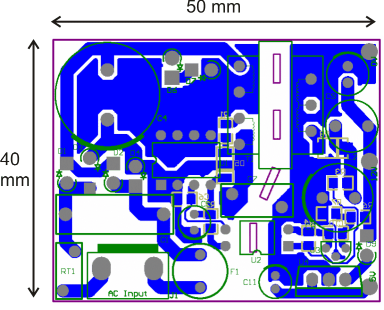
As can be seen in the picture, the circuit is indeed very small, compared to the power that is available from it. It's just 50 by 40 mm in its dimensions.
The circuit diagram is very easy to understand, let's study it with the following points:
1) SMPS using VIPer22A
Looking at the figure we can easily see that the configuration does not involve too many stages or parts.
The input mains AC, as usual is first rectified using ordinary 1N4007 diodes which is fixed in the bridge network mode.
The rectified high voltage DC is filtered using the high voltage capacitor.
The next stage is the crucial one which incorporates the outstanding chip VIPer22A manufactured by ST Microelectronics.
The IC alone functions as the oscillator and induces a frequency of around 100 KHz into the primary winding of the ferrite E core transformer.
The IC is absolutely rugged and is internally protected from sudden voltage in rush and other voltage related component hazards.
The IC also incorporates built in over heat protection which makes the IC virtually indestructible.
The voltage induced at the input is effectively stepped down at the output winding, due to low eddy current losses, about 1 amp current becomes available from a relatively tiny ferrite transformer.
With the coil specs shown the voltage is around 12 and the current is around 1amp.
A special feedback circuitry is also included in the circuit for maintaining high degree of protection and power saving features.
The feedback loop is implemented via an opto-coupler which becomes active during abnormal circuit conditions.
When the output voltage tends to rise beyond the set threshold the feed back loop becomes operative and feeds an error signal to the IC FB input.
The IC instantly comes into an corrective mode and switches off the input to the primary winding until the output returns to the normal range.
You may also want to read this: 24watt, 12V, 2 amp SMPS using a single IC Most recommended for you.
Circuit Diagram

PCB Layout
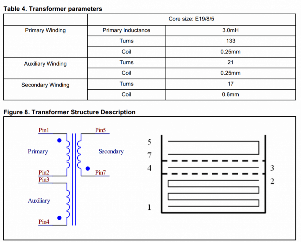
Transformer Winding Data
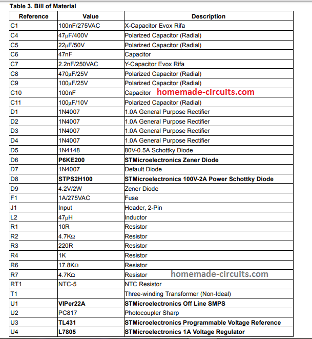
Parts List
For the original datasheet please refer to this article.
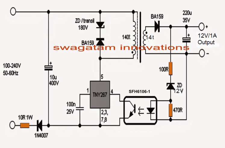
2) Another 12V 1 amp simple SMPS using IC TNY267
How it Works
The simple smps circuit shown above uses the popular tiny switch IC TNY267. It is a tiny mosfet based 120V to 220V switching oscillator IC which only requires configuring with a ferrite transformer and a stepped down Vdd operating voltage.
The design is so simple that a mere visualization of the schematic is enough to tell us the functioning details quickly.
The stepped down start voltage is acquired from stabilizing network using a 180V zener diodes and the fast recovery diode BA159 after rectifying the mains 220V through a 1N4007 diodes and the 10uF/400V filter capacitor.
As soon as this voltage is applied to the IC, it begins oscillating and its internal mosfet begins switching the ferrite transformer primary at the predetermined oscillating frequency.
Being a flyback design, the secondary also starts conducting during the OFF cycles of the primary through mutual induction and generates the required 12V voltage at the output side.
This voltage may not be stabilized, therefore an opto-coupler based feedback is used and the link is configured with the exclusive shut down pinout 4 of the IC.
This ensures that the output never exceeds, and remains fixed at 12V 1 amp proportion.
Transformer Winding Data
The transformer winding is actually quite straightforward, and may be done in the following manner. Keep in mind that the black dots indicate the start points of the winding which is very important, and must be strictly followed while winding the transformer.
The primary wound using 36 SWG super enameled copper wire upto 150 turns, while the secondary is wound using 26 SWG wire upto around 12 to 15 turns.
The core can be a standard E19 type ferrite core having a bobbin with central core cross section area of approximately 4.5mm by 4.5mm.



Questions & Answers
yes you can achieve it by adding additional winding layers connected parallel to the existing secondary layer inside the transformer
Hi P Pandey,
You can either connect three 1N5402 diodes in series with the battery and directly connect it with your phone, it will hopefully start charging it.
Alternatively you can just include a 4 ohm, 2 watt resistor in series with the battery positive and connect it directly with the cell phone for initiating charging of the phone.
Dear Sir,
I am student of B.tech ECE.. I was trying to make SMPS of 150W (of voltage range 60 – 210 Volts DC & about 1 Amp. current). You are kindly requested to guide me for the same & oblige. My main problem is which transformer is to be used & the feedback circuit. I shall really appreciate if you could give me entire circuit.
Thanks & Regards,
Aseem Mittal (09417753155)
aseem.mittal19@gmail.com
Dear Aseem,
I don't have much idea about the transformer winding details, so I am sorry I won't be able to help with the project.
By the way what is the output voltage of the design?
hello sir,
From where can i get this type of transformer.
hello hiren,
you won't get it readymade, you will have to make it with the help of the given date.
Hello Pankaj,
555 is an evergreen versatile IC and will be there for at least another 50 years…may be its not available in your area.
Anyway, in your transistor circuit you can add a 100k pot in series with one of the transistor base resistors, this will give you an option for the required adjustments.
Hi Sir
i want a temperature control circuit for incubator.do u have any circuit diagram.
Hi Yasir, you can refer to this article:
https://www.homemade-circuits.com/2011/12/how-to-build-simple-electronic.html
Circuit diagram isn't completely visible, it got clipped from top.
please check it now.
What should be the changes to make it 12V, 2amp
make the secondary winding using two wires wound simultaneously…it's also called bifilar winding.
I want to make 5 to 12 volt smps work on 60 volt a/c input. may anyone tell me how to make it ?
you can try the following circuit
https://www.homemade-circuits.com/2014/03/12v-5-amp-transformerless-battery.html
sir i have an ic cd6283cs audio amplifier circuit. i give 12v to use this circuit it gets heated up if input is more. and in datasheet it is given that it can handle upto 171v and utput 1500watts. it will be like that? on 12v only it gets heated then how come it will survive on 171v?
Rushi, the datasheet which you have referred to is of a TAZ (transient absorption zener) not your amplifier IC…..
the datasheet for your IC is probably not available on the net, so can't suggest much about it.
Mr. Swagatam this thing is looking great for starter's scenario, can you give the detail about each components you have used in this circuit?
Thanks Mr. Akuu, I'll try to update the required explanation soon….
Dear Mr. Arya, it's not so critical, you can make it by winding a reasonably thick magnet wire over any type of ferrite core. Through some trial and error make the number match the shown value approximately….I think about 50 turns using 25SWG wire on any ferrite core would be good enough
Hello Sir
Can I have gerber data and BOM of the same as I'm not able to identify the component out here.
Kindly reply as soon as possible.
Thank you.
Regards,
Bharat Surani
+91787998867
suranibharat4@gmail.com
Hello Bharat,
Please click on the diagram to enlarge, you'll able to see the part specs in detail.
I am sorry a gerber file would be difficult from my side.
for more info and BOM you can refer to this original pdf source:
http://www.google.co.in/url?sa=t&rct=j&q=&esrc=s&source=web&cd=5&ved=0CDYQFjAE&url=http%3A%2F%2Fapplication-notes.digchip.com%2F005%2F5-10593.pdf&ei=UTaaVYWdF4uZuQTyvYOwBQ&usg=AFQjCNETxUPxGfwhkqnl61rOFrs0PtJXRw&sig2=t-GcqS0gHIw0fPxqKNz4NA
Hello Sir
How can I increase current rating?
1amp is the max current which cannot be increased with this IC
is there any replacement of D8-STPS2H100? As it is not available in market.
Kindly reply as soon as possible.
Google for "700v mosfet", you will find many options to choose from….any mosfet with 700V and 5 amp would be ok
sorry… please ignore above comment
you can try a BA159 diode
Is there any other option for increasing current?
the IC is specified to produce not more than 1amp, so it's not possible
and about, BA159 is of 1A only. Will it be fine with replacement of 2A schottky diode?
you can test it, if it heats up then we can look for some other option.
well in that case 1N4007 will also be fine… rihgt?
1N4007 is not a fast switching diode, BA159 is a fast switching diode.
But I have seen many SMPS use ordinary diodes such as 1N5408 etc at the output so you can try a 1N5408 which is same as a1N4007 but much higher in amps.
Can I got for SR2100?
yes it will do.
hello sir,
i have design same circuit 12v,1 Amp SMPS. But the problem is when i connect the load and it will consume more then 100mA current then voltage get drop to 11 volt.so could i maintain constant voltage 12 volt along with the load. or if voltage drop does it effect on stability.
hello shaikh,
that should not happen, if you have made it exactly as explained above then the smps should be able to withstand full 1 amp current… at 100mA the voltage should not drop…
the wire gauge determines the amp capacity of the smps, are you sure you used the specified wire dimensions?
hi sir,
i m facing problems in calculating primary , secondary and auxiliary winding's.please help me to calculation of exact winding's.
Kindly reply as soon as possible.
thank you
Hi Shaikh,
all the details regarding the trafo winding are furnished at the bottom of the article, please click on the last diagram, you'll find all the required data and the related layout diagram.
Hello Sir
I have implemented same design on PCB. I'm facing some problem. Like 5 V are coming perfectly on controller board, but when I connect relay board with it, and switch any two relay even, power supply is getting restart. Why this is happening so, i did't got any reason, can you pl help us?
Kindly reply as soon as possible.
Hello Bharat,
check the current consumption of the relay coil, by connecting a DC ammeter in series with the relay coil.
or may be you have not made the circuit correctly as per the given instructions.
it is around 50 mA per relay and I have only used 7 relays.
that's equal to 350 mA which is perfectly within the range of the design…it would be difficult for me to troubleshoot it from here…
the winding has polarity (start/finish) and that can be crucial, please check it and also try rewinding the secondary by using two strands of wire in parallel instead of one.
Hello Sir
I got the current value by changing transformer winding's SWG, but one more problem has taken place, that SMPS is getting too hot, and after that it is restarting it self.
What can be the problem?
Hello Bharat,
I think the transformer is not wound correctly, please see the black dots those indicate the "start" of the winding….. did you follow those correctly?
the IC will reset if it detects overload…. which could be either at the output in the form of an actual overload or a wrongly wound primary….
OK got it….alternatively you can attach a small aluminum heatsink over the IC…this will stop the circuit from resetting….
hi sir,
i m facing problems in calculating primary , secondary and auxiliary winding's.please help me to calculation of exact winding's for 5 V,1 A smps.
Kindly reply as soon as possible.
thank you
Shaikh, you just have to vary R6 for getting any desired voltage in the range…the winding can be as suggested in the article.
hai,
I am new, I designed this above circuit. I got some issues VDD Voltage is 4.1 v some viper is not switching,
can any one guide me.
thanx
Sir how may tuns includ in secandry need 2 amp??