In this post I have explained how to make 2 accurate long duration timer circuits ranging from 4 hours to 40 hours, which can be upgraded further for getting even longer delays. The concepts are fully adjustable.
A timer in electronics is essentially a device which is used for producing time delay intervals for switching a connected load. The time delay is set externally by the user as per the requirement.
Introduction
Please remember that you can never produce long accurate delays using only a single 4060 IC or any CMOS IC.
I have confirmed practically that beyond 4 hours IC 4060 begins deviating from its accuracy range.
IC 555 as a delay timer is even worse, it's almost impossible to get accurate delays even for an hour from this IC.
This inaccuracy is mostly due to capacitor leakage current, and inefficient discharging of the capacitor.
ICs like 4060, IC 555, etc basically generate oscillations which are adjustable right from a few Hz to many Hz.
Unless these IC are integrated with another divider counter device such as IC 4017, getting very high accurate time intervals may not be feasible. For getting 24 hour, or even days and week intervals you will have integrate a divider/counter stage as shown below.
In the first circuit we see how two different modes of ICs can be coupled together to form an effective long duration timer circuit.
1) Circuit Description
Referring to the circuit diagram.
- IC1 is an oscillator counter IC consisting a built in oscillator stage and generates clock pulses with varying periods across its pins 1,2,3,4,5,6,7,9,13,14,15.
- The output from pin 3 produces the longest time interval and therefore we select this output for feeding the next stage.
- The pot P1 and the capacitor C1 of IC1 can be used for adjusting the time span at it pin 3.
- The higher the setting of the above components the longer the period at pin #3.
- The next stage consists of decade counter IC 4017 which does nothing but increase the time interval obtained from IC1 to ten folds. It means if the the time interval generated by IC1s pin #3 is 10 hours, the time generated at pin #11 of IC2 would be 10*10 = 100 hours.
- Similarly if the time generated at pin #3 of IC1 is 6 minutes, would mean a high output from pin#11 of IC1 after 60 minutes or 1 hour.
- When power is switched ON, capacitor C2 makes sure that the reset pins of both the ICs are appropriately reset, so that the ICs begin counting from zero rather than from some irrelevant intermediate figure.
- As long as the counting progresses, pin #11 of IC2 remains at logic low, such that the relay driver is held switched OFF.
- After the set timing lapses, pin#11 of IC2 goes high activating the transistor/relay stage and the subsequent load connected with the relay contacts.
- The diode D1 ensures that the output from pin#11 of IC2 locks the counting of IC1 by providing a feed back latch signal at its pin #11.
Thus the whole timer latches until the timer is switched OFF and restarted again for repeating the entire process.
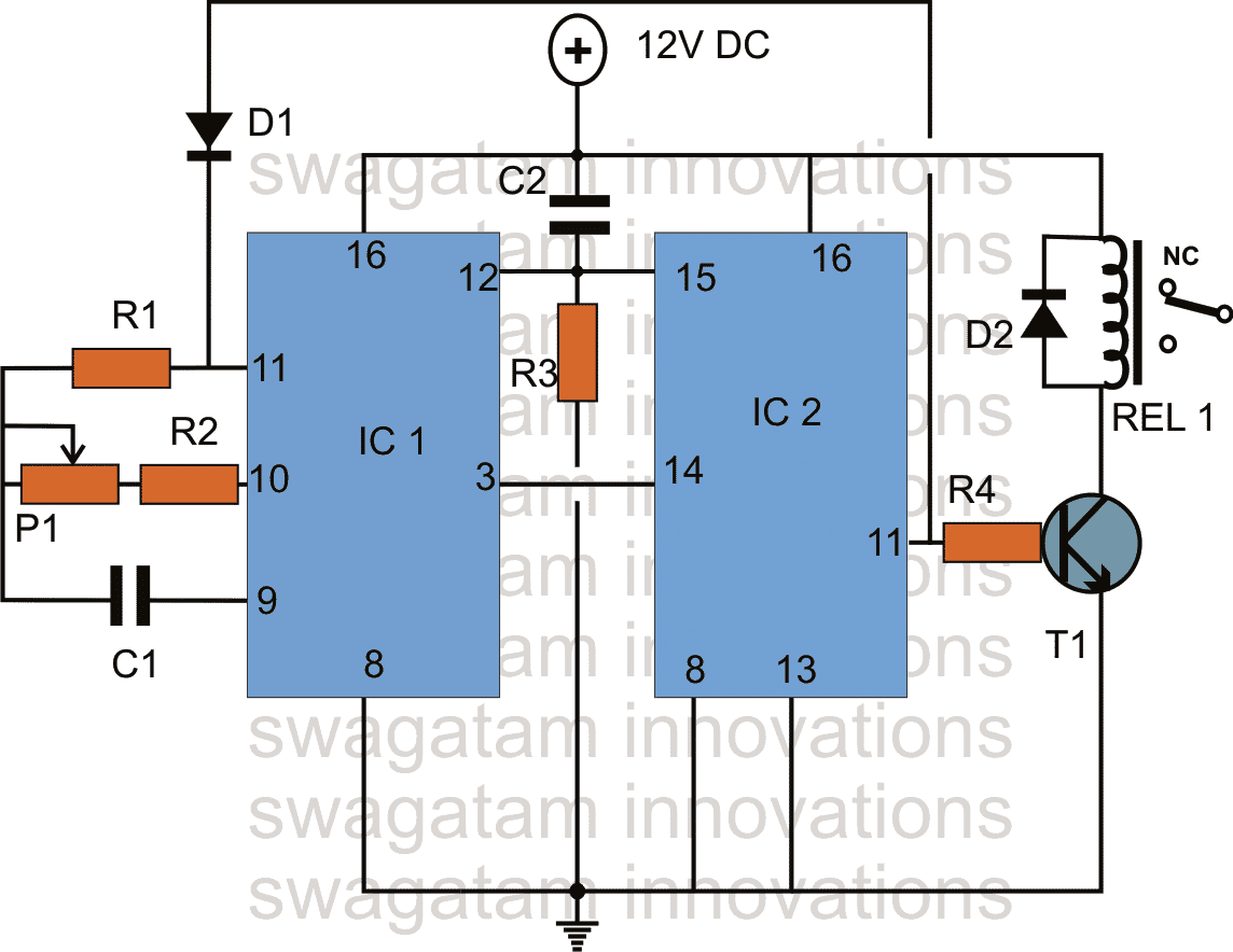
Parts List
R1, R3 = 1M
R2, R4 = 12K,
C1, C2 = 1uF/25V,
D1, D2 = 1N4007,
IC1 = 4060,
IC2 = 4017,
T1 = BC547,
POT = 1M linear
RELAY = 12V SPDT
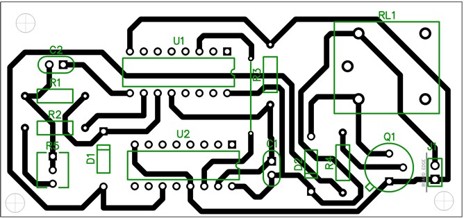
PCB Layout
Formula for Calculating Delay output for IC 4060
Delay Period = 2.2 Rt.Ct.2(N -1)
Frequency = 1 / 2.2 Rt.Ct
Rt = P1 + R2
Ct = C1
R1 = 10(P1+R2)
Adding Selector Switch and LEDs
The above design could be further enhanced with a selector switch and sequential LEDs, as indicated in the following diagram:
How it Works
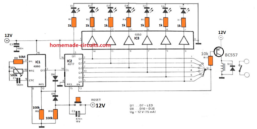
The main element of the timing circuit is a 4060 CMOS device, which is made up of an oscillator along with a 14 stage divider.
The frequency of the oscillator could be tweaked through potentiometer P1 in order that the output at Q13 is around a single pulse each hour.
The period of this clock beat could be extremely quick (around 100 ns), as it additionally resets the whole 4060 IC by way of diode D8.
The 'once each hour' clock pulse is given to the 2nd (divide-by-ten) counter, the 4017 IC. One of several outputs of this counter is going to be logic high (logic one) at any given instant.
When the 4017 is reset, output Q0 goes high. Right after one hour, output Q0 will turn low and output Q1 may become high, etc. Switch S1 as a result allows the user to choose a time interval through one to six hours.
When the chosen output becomes high, the transistor turns off and the relay gets switched OFF (thus turning off the connected load).
Once the enable input of the 4017 is furthermore attached to the wiper of S1 any succeeding clock pulses turns out to have no impact on ihe counter. The device will consequently continue to be in the switched OFF condition until the reset switch is presed by the user.
The 4050 CMOS buffer IC along with the 7 LEDs are incorporated to offer indication of the range of hours which may have essentially elapsed. These parts could, obviously, be removed in case an lapsed time display is not needed.
The source voltage for this circuit is not really crucial and could be cover anything from 5 and 15 V, The current usage of the circuit, excluding the relay, will be in the range of 15 mA.
It is advisable to pick a source voltage that may be matching the specifications of the relay, to ensure that any problems are avoided. The BC 557 transistor can handle a current of 70 mA, so make sure the relay coil voltage is rated withing this current range
2) Using Only BJTs
The next design explains a very long duration timer circuit which uses only a couple of transistors for the intended operations.
Long duration timer circuits normally involve ICs for the processing because executing long duration delays requires high precision and accuracy which is possible only using ICs.
Achieving High Accuracy Delays
Even our very own IC 555 becomes helpless and inaccurate when long duration delays are expected from it.
The encountered difficulty for sustaining high accuracy with long duration is basically the leakage voltage issue, and the inconsistent discharging of the capacitors which leads to wrong starting thresholds for the timer producing errors in the timing for each cycles.
The leakages and inconsistent discharge issues become proportionately bigger as the capacitor values get bigger which becomes imperative for obtaining long intervals.
Therefore making a long duration timers with ordinary BJTs could be almost impossible as these devices alone could be too basic and cannot be expected for such complex implementations.
So How can a Transistor Circuit Produce Long Accurate Duration Time Intervals?
The following transistor circuit handles the above discussed issues credibly and can be used for acquiring long duration timing with reasonably high accuracy (+/-2%).
It's simply due to effective discharging of the capacitor on every new cycle, this ensures that the circuit begins from zero, and enables accurate identical time periods for the selected RC network.
Circuit Diagram
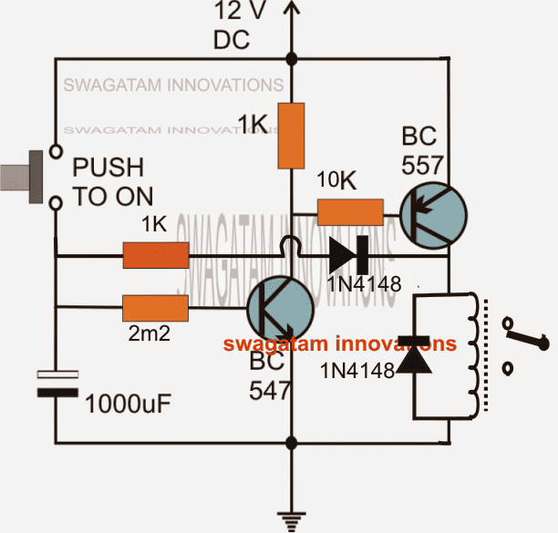
The circuit may be understood with the help of the following discussion:
How it Works
A momentary push of the push button charges the 1000uF capacitor fully and triggers the NPN BC547 transistor, sustaining the position even after the switch is released due to the slow discharging of the 1000uF via the 2M2 resistor and the emitter of the NPN.
Triggering of the BC547 also switches ON the PNP BC557 which in turns switches ON the relay and the connected load.
The above situation holds on as long as the 1000uF is not discharged below the cut off levels of the the two transistors.
The above discussed operations are quite basic and make an ordinary timer configuration which may be too inaccurate with its performance.
How the 1K and 1N4148 Work
However the addition of the 1K/1N4148 network instantly the transforms the circuit into a hugely accurate long duration timer for the following reasons.
The 1K and the 1N4148 link ensures that each time the transistors break up the latch due to insufficient charge in the capacitor, the residual charge inside the capacitor is forced to discharge fully through the above resistor/diode link via the relay coil.
The above feature makes sure that the capacitor is completely drained off and empty for the next cycle and thus is able to produce a clean start from zero.
Without the above feature the capacitor would be unable to discharge completely and the residual charge inside would induce undefined start points making the procedures inaccurate and inconsistent.
The circuit could be even further enhanced by using a Darlington pair for the NPN allowing the use of much higher value resistors at its base and proportionately low value capacitors. Lower value capacitors would produce lower leakages and help to improve the timing accuracy during the long duration counting periods.
How to Calculate the Component Values for the Desired Long Delays:
Vc = Vs(1 - e-t/RC)
Where:
- Vc is the voltage across the capacitor
- Vs is the supply voltage
- t is the elapsed time since the application of the supply voltage
- RC is the time constant of the RC charging circuit
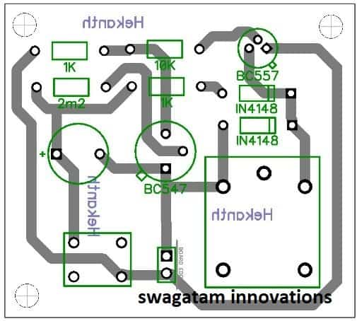
PCB Design
Long Duration Timer using Op Amps
The disadvantage of all analogue timers (monostable circuits) is that, in an effort to achieve fairly long time periods, the RC time constant needs to be correspondingly substantial.
This inevitably implies resistor values of greater than 1 M, that may result in timing mistakes caused by stray leakage resistance within the circuit, or substantial electrolytic capacitors, that similarly can create timing problems because of their leakage resistance.
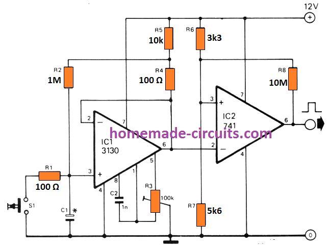
The op amp timer circuit shown above accomplishes timing periods as much as 100 times more time compared to those accessible using regular circuits.
It achieves this by lowering the capacitor charging current through a factor of 100, consequently improving the charging time drastically, without requiring high value charging capacitors. The circuit works in the following way:
When the start/reset button is clicked C1 gets discharged and this causes output of op amp IC1, which is configured as a voltage follower, to become zero volts. The inverting input of comparator IC2 is at a reduced voltage level than the non -inverting input, hence the output of IC2 moves high.
The voltage around R4 is around 120 mV, which means that C1 charges via R2 with a current of approximately 120 nA, which apprers to be 100 times less than what could be attained in case R2 had been attached direct to positive supply.
Needless to say, if C1 had been charged through a consistent 120 mV it could rapidly achieve this voltage, and stop charging any further.
However, the lower terminal of R4 being fed back to the output of IC1 ensures that as the voltage across C1 goes up so does the output voltage and therefore the charging voltage given to R2.
Once the output voltage climbs to approximately 7.5 volts it surpasses the voltage refernced at the non-inverting input of IC2 by R6 and R7, and the output of IC2 becomes low.
A tiny quantity of positive feedback supplied by R8 inhibits any kind of noise existing on the output of IC1 from getting boosted by IC2 as it moves from the trigger point, because this normally produce false output pulses. The timing length can be calculated by the equation:
T = R2 C1( 1 + R5/R4 + R5/R2) x C2 x ( 1 + R7/R6)
This may appear somewhat complex, but with the part numbers indicated the time interval can be set as long as 100 C1. Here C1 is in microfarads, let's say if C1 is selected as 1 µ then the output time interval will be 100 seconds.
It is very clear from the equation that it is possible to vary the timing interval linearly by substituting R2 with a 1 M potentiometer, or logarithmically by using a 10 k pot in place of R6 and R7.
Long Duration Timer using LDR for Day Night Sensing




Questions & Answers
You can alter the timing by increasing or decreasing the value C1 and the 1M pot.
Connect more number of 1u parallel to C1 and adjust the 1M pot by some trial and error for geting the desired timing.
Alternatively the formula for timing may be seen here:
https://www.homemade-circuits.com/2012/01/how-to-make-simple-versatile-timer.html
pin11 4017 is the output. pin3 of 4060 will blink but at the rate of minutes as per the setting of the above timing parts.
pin7 of 4060 will blink faster, which indicates the timer is working corectly.
The relay should be 12V, the supply voltage should be 12V and the transistor any NPN type general purpose.
You can connect LEDs with series 1K resistor across pin7 and ground of IC4060 and same for IC 4017 at its pin11.
The LEDs will provide the appropriate indications regarding the working of the circuit.
Hi Swagatam,
How could I alter this circuit to delay 1Hr OFF to ON, 1Second of being ON then OFF, and continue to cycle continuously (1hr OFF 1sec ON)?
Thanks for your help. Your a legend!
Hi Jason,
Thanks! You can try the following circuit, it will suit your need well:
https://www.homemade-circuits.com/2012/04/how-to-make-simple-programmable-timer.html
Hai, I want the relay to activate for 15 hours and de-activate for 9 hours. so wat are the changes I have to made in the above circuit?? Pls help…
Hi, you will need to build the following circuit for achieving it, not the above one:
https://www.homemade-circuits.com/2012/04/how-to-make-simple-programmable-timer.html
so, if I want the relay to activated for 9 hrs means i have to set 54 minutes in the IC1 with the help of POT P1. So by rotating the P1 knob, how I can able to know that i adjusted the knob for 54 mins??
And u said me to connect the clock's alarm output positive trigger to pin12 of IC4060 via a 1uF capacitor. but the +12v dc is already connected at the junction of pin12 of IC1, pin15 of IC2 via 1uf capacitor. so if I connect the alarm output at this junction means will the relay get active at the alarm time??
you will have set the pot appropriately or opt for a fixed resistor in that place through some experimentation.
First try any arbitrarily chosen small value resistor, note after how many seconds pin3 of 4060 becomes high. After you get the value you can calculate the 54 minute resistor accordingly by cross multiplication:
selected resistor/R = "x"seconds/54 x 60
where R is the unknown resistor, x seconds is the noted timing, the selected small value resistor could be 10K (use only one resistor)
….yes the alarm output should be connected to pin12 of 4060 via a 1uF capacitor, this reset the whole action and itiate the timing from zero.
Relay will get activated if a PNP transistor is used at pin11 of 4017
ok. will a ordinary analog or digital table clock which is running on 1.5v battery work with the above circuit for my requirement??
No, the trigger will require at least 5V at pin12.
however the input could be amplified using a BC547 transistor, whose emitter could be used for triggering pin12 of 4060, collector could be connected to the IC supply, base to clock trigger via a 10k resistor.
i made a diagram as u said. pls check it whether it is correct…
imgur.com/OVZE2oZ
I placed a 10k resistor next to 1k for calculatig time. is that correct??
And u told me use a PNP transistor at pin11 of 4017 to activate the relay at alarm timing. so do i need to replace that BC547 with BC557??
BC547 collector should join with positive and the emitter to the 1uF capacitor…
If you are using a fixed timing resistor at pin2 then only one resistor should be included to make the calculations easier, if two are used then use the sum of both in the calculations.
…..also connect a 100k resistor across emitter of BC547 and ground so that the capacitor can discharge for the repeat cycles.
pin2 !!!?? u mean pin10, right??
And i did modification as u said. pls check it…
imgur.com/kuBCE46
Thn u said "Relay will get activated if a PNP transistor is used at pin11 of 4017". sry, i didnt understand that. pls explain that…
pin2 was in response to the PIR circuit not this one, when you said the 555 was get hot.
the diagram is correct now.
Yes use BC557 instead of BC547
Initiate (switch ON) the circuit exactly at the time when you want the clock to trigger, this will reset the timer to start, the relay will switch ON, and the circuit will start counting for the desired 10 hour period. After this you can leave the circuit for automatic operations everyday.
I remove IC# 2 and P1, and it work well,.. but replacing R2 with 2M ohms, it activates relay after 3 hours, but never deactivate,..
remove D1 for getting an alternate 3 hour ON, 3 hour OFF switching from the circuit
Hello sir, please i need a circuit to turn off a relay after 14 or 15 hours … Thanks.
Hello Amir, you can use the above circuit for the application, use a BC557 instead of the shown BC547 and connect the relay across its collector and ground.
Swag…
It'd be neat if you devised a circuit that could:
1. Detect Darkness
2. Wait an adjustable amount of time, say 1-3 hours
3. energize a light, or relay
4. Stay on for an adjustable amount of time 3-8 hrs
That'd be a huge improvement over typical solar garden lights, as they typicall come on too early, and stay on too long.
Thanks
Hi Unknown , I'll try to design it and post it in this blog soon.
Hi sir i need ur help on the circuit i have constructed as per the above diagram but i coudnt get response or out put …
Hi Subramania, the output will be activated only after the set time has elapsed….you can connect an LED at pin3/ground via a 1K resistor of the IC4017..this LED will light up at switch ON and will shut off after some time indicating that the time period is sequencing. or you can connect such LEDs across all the outputs of the IC4017 for a clearer view and confirmation about how the time period may be proceeding.
Hi!
Can I use 555 monostable circuit for charging my battery for about one hour.i think that it will be not much accurate I don't want it to be much accurate but just wanted to charge my battery for about one hour and then the relay shut off the charger.
hi, yes you may do it if you know the approximate time the battery would take to get charged optimally…
Thanks..
Sir, i want to use the ckt for automatic ON/OFF air cooler 240V, 11-18A . How can i do it ? is
step up of relay out put required ?
Abhijit, you can use the above circuit for your purpose, the relay contacts will need to be wired with AC220V and the air cooler socket…..just disconnect the mains wire connected with any one of the socket terminals and connect it to the relay pole, connect another wire from the N/O contact of the relay and join it back at this socket terminal.
sir, i want to know time duration formula of this timer ckt.plz help me.
you can find it here:
https://www.homemade-circuits.com/2012/01/how-to-make-simple-versatile-timer.html
C will be in Farads
Dearest Swagatam,
So this circuit will work with 5v at input, and deliver 5v to the relay, so that I can use a homemade SSR? I'd like to use it to turn off my basement lights a few hours after they are turned on. No one ever remembers to turn them off, and I find them still burning days or weeks later. That is not acceptable, and yet PIR switches are unacceptable for this purpose, because the area is so huge…
Dearest Tom, yes definitely you can use it for the intended purpose, however an SSR could be unnecessarily costly, instead you can try the second circuit from the following link, which looks much cheaper and yet effective:
https://www.homemade-circuits.com/2013/07/simple-triac-timer-circuit.html
Hi swagatam sir.I want a timer which should off for 2 seconds in 24 hours and drive relay with it.how can i achieve this with the above circuit.
Hi Kishore, you can try the above shown circuit, just add a 100uF capacitor in series with the transistor base, and tune the 4060 IC to produce a 1.2 hour time pulse
Dear i need a diagram timer for 45minute on and 45m 0ff and so on
Dear swagatam how can i change it to 30minute ON 30mn OFF and so on
use the above circuit without the 4017 IC…connect the transistor relay driver directly with the pin#3 of 4060 and tune the IC to produce 30 minute frequency or 45 min…
How to make 6 months timer circuit?
Swagatam, another great circuit, follow a lot of yours.
I have 2 questions, what's the current draw of the circuit? I suspect it's extremely low since its only a timer.
2Nd. I want the timer to control my solar panels because the way the sun comes around my house I have to keep moving my panel from 2 spots the relay would need to support 37v Min, and 8amps Min also needs to switch every 6 hours a timer is my only option as one panel gets full sun from 6am till 12pm then the other from 12pm till 5:30pm however I can't be at home to move it haha but I can't run one panel in each spot together as it's to much for my controller so a timer would be good to switch one panel on at a time
Thank you unknown,
however a timer is not what may be appropriate for your purpose.
Sorry I could not correctly understand why you cannot connect both the panels in parallel and use it with the existing controller…..??
If you are thinking that your controller would burn then that's not correct, as long as the specs of both the panels are similar.
It's the connected output load that matters, not the input wattage, if the output load exceeds above the controller's handling limit in such a case there could be a danger to the controller, having said that today all controllers have built-in overload protection so under any circumstances the device is never at a risk of burning.
So I think you should connect the panels in parallel and enjoy maximum power from them, and in fact prevent unnecessary wastage of energy:)
Yes that's correct my mppt controller supports 260w at 12v 20amps output, my panel is 250w the controller also supports up to 150v voc input. It does have a cut out when the power exceededs it's limit then connects back once panels fall back under, I just thought I wouldn't want to risk it for the price of the controller I paid I wanted to be safe then sorry.
I do also have my panels the same specs and brand so they don't pull each other down and config issues. I think it would be okay since panel on the side in the mornings on a nice sunny clear day only produces 3amps max since its not direct sunlight. However I have seen it peak to 19.5amps if both did that it would be a massive 40amp on the output and 16amp on the input for a 20amp controller?
The input current will not harm your controller as long as the following two things are maintained, as per the specs of the controller:
1) Don't allow the connected output loads to exceed 250 watts, and
2) Don't allow the input voltage from the panel to exceed 150V.
If the above two criteria are maintained there's no way your controller could get damaged.
There's only about 60v max voltage going into the controller.
It's connected directly to a battery bank which is fused, but there's a 600w inverter connected to the battery bank? Are you saying I can't exceed my inverter past 250w?
OK so if the inverter is linked with your battery, it would be the battery which would supply the power to the inverter, not the controller, so the 250 watt load issue is not related with the charger controller rather the battery
The controller would be only associated with the charging current which I assume would constitute much less than the 250 watt limit…so under any circumstances your controller appears to be safe and sound, therefore combining the two panels together is perfectly advisable.
Thanks swagatam it's working great, currently we are in summer over here in Australia sun rises at about 5:30am I get 16-18amps from then till 6pm I have however had it jump to 20amps :/ both panels got sun for a bit then it went cloudy and blocked one panel dropped to about 10amps I've yet to experience the controller to cut out and see how it handles over current, don't want it to constantly be cutting out because it hits past 20amps output, or is this not how mppt works? Does it just waste the extra current to heat?
Sorry to go way off topic from your circuit, but is it possible to have 2 separate pv arrays 2 separate controllers (1 for each array) 2 separate battery banks (1 for each again) but one inverter both banks parallel to the inverter? It will be a 24v set-up.
Thanks Anton, I am glad to know this.
An MPPT will never waste anything through dissipation, however if it gets an input beyond its rated specs then it will simply block the excess power…which is I think as good as wasting power.
So if you want to take the maximum advantage of the available resources then either you can go for an upgraded or higher rated controller…so use separate devices for the two panels, as you have already planned to do.
Using two separate controllers and batteries for the two panels will not harm anything, just increase the set up cost, you can surely go ahead with it, no issues.
Thanks for all the info, I'm still deciding on 2 separate controllers or one single big one the maximum amp controller I've seen is 40A which is why I'd probably need 2 so the batteries charge up within the time of the sun being out.
As for my 20A controller I've got 2 panels connected for 12v a 235w panel and a 250w panel as you said it will only use what it needs and I can now see that because when the batteries are nearly charged the amps drop to only a few amps but if I put a load on, the amps go up. Having the panels in parallel seem to be better than series as they tend to drag each other down a bit having 66vmp and 8.1imp the controller doesn't hit 20amps whereas in parallel it will sit at 20amps with 8imp and 33vmp each panel it can utilise all the current from both panels then convert some voltage to make it to 20amps.
Do you think it's possible to earth an inverter that has live and neutral-live? Is there a way? I will eventually get an inverter that has 0v neutral but at the moment my 600w inverter is doing good, just want to leave it in permanent with earth protection but it has no neutral as both wires will give you a zap.
Thanks for updating your progress!
yes connecting the panels in parallel would give better results, especially if the controller is an MPPT type so please make sure it is an MPPT if you happen to buy a new one.
Your present inverter output should not be associated with an "earth" connection in any manner otherwise that would result in a short circuit or heavy power losses….not recommended unless it has a neutral specified with a permanent 0V
Yes I only buy mppt controllers, they are the best.
Would any electronic device turn this wire into a neutral maybe like an isolation transformer? Or no point?
Not to mention if it was tied to earth any device with a metal chassis will be live. I would like to put a rcd on the ac side but there would be no point because there's no earth I want to protect against a malfunction that could cause a shock or is there no need? It's only a 600w inverter.
Instead of worrying about the inverter earthing, it would be easier to "earth" the appliances appropriately…so in case of a leakage the appliances would produce no shock, as we normally implement in our homes.
Yeah the appliances are earthed I don't have the earth going to the chassis of the inverter though it just goes into my switchboard then down to an earth rod in the ground. Should I also allow the metal chassis of the inverter to be connected to earth or will this cause an issue if the inverter ends up 'live' to the case it will send it to all the appliances?
Sorry for all the questions and going off topic.
I think it would be better to keep the inverter away from the house earthing, because anyway it's not so crucial to earth the inverter as long as the appliances are earthed
can i get 30 minutes Auto On and Off from this circuit
for 30 min ON/OFF the 4017 may not be necessary…you can achieve it with the 4060 stage itself…connect the relay driver with the pin#3 of the IC 4060 for the required delays by adjusting the pot accordingly
Hi Swagatam,
I'm looking at building a circuit the has 2 timers.
– 1 switches on for 12 hours and off for the remaining 12 hours.
– the other switches on for 15 minutes and off for 45 minutes.
can it be done with power source 12VDC?
I'm a newbie. don't know much about electronics. I used an arduino to do this but I'm looking at a much cheaper option.
Hi CJ, you can build two of the following circuits and adjust their controls accordingly for the results:
https://www.homemade-circuits.com/2012/04/how-to-make-simple-programmable-timer.html
However If you are a newcomer then you may find it difficult to build it successfully
Hello sir..
I m making a solar street light and i want that when our lights is switched on, and after about 4 to 5 hours it will dim the light automatically..
Plz help me to make that type of circuit
Hello Harjinder, you can connect a 4060 timer stage in between the light and the solar circuit through which you can set the required switch OFF delays.
If possible I'll try to present it in my website soon.
Good afternoone Sir!
I want to use this timer circuit for my solar street light in two ways:-1st )for 24v and 2nd)36v.
which types of relaies must I use and which parts to be changed?
Secondly,Do you have a circuit which can 1st Detects a Darkness then after an adjustable time
give a light for some hours and at the end go to OFF position?
Greeting,Beni
Good day Beni,
I think you should try the following concept:
https://www.homemade-circuits.com/2016/12/automatic-food-warmer-lamp-timer.html
here you just have to remove the entire PIR section, connect an LDR across R6 and 7805 positive, and connect a 1M across R6 and ground, and use only the pin#3 relay driver section.
once you implement this…you will be able to precisely achieve what you are looking for…
Dear Swagatham,
can you please modify this circit as follows
I have a 12hr mode Quarts clock with needles. My idea is to fix 12 LED's at each hour positions. One LED should lit at a time. Eg, if time is 3'O Clock, third LED should glow. After 1hr 4th LED should lit. This process continues.
By this arrangement, it is easy to understand the time at night by the LED position.
I know, CD4017 have only 10 otputs, I think, two CD4017 can be cascaded to obtain 12 outputs. If yes, design that way, otherwise, use any different IC have 12 outputs.
Dear Anil, you can do it the following way:
connect the pin13 of the first IC 4017 with its own pin11, which is last or the 10th output.
connect this junction with the base of a BC547 through a 1K resistor, connect the collector with pin#8 of the second 4017 IC. connect emitter with ground.
finally connect the pin#7 of the second 4017 with pin#15 of the first through a 1K resistor, remember you must disconnect the pin#15 of the first IC 4017 from ground before doing this.
also make sure to connect a 0.47uF capacitor positive to Pin#15 of the first IC.
Pi#15 of the second IC can be connected with ground, but remember to connect pin#14 of both the ICs together.
Good evening. Pls I need a circuit that can switch between 3loads with 4 hours intervals
you can use the same circuit as shown in the above article, with the following modifications:
use 2, 4, 7 as the outputs for the loads, and connect pin#10 with D1 anode….ignore pin#11 keep it unconnected.
set pin#3 of IC 4060 for 3 hour clocks
Thanks admin! Pls am using Proteus on my PC before but I mistakenly uninstall it and I was unable to install it back……
sorry I do not have any solution to that problem!!
Thanks for your response at admin…
you are welcome!
Hi, Admin,
I need 3 kinds of circuit which is for the paddy field pest control light(LED) up to 40LED which can be run on 9V battery or 6v AA battery.
Conditions are below.
1) Switch on the unit(40led light run with 9V or 6v battery) and it should off 2hrs 30min to 3hrs.
2) Auto switch on when out door light dims then Auto off after 2hrs 30min to 3hrs.
3) sl no 2 with solar charger..
Purushottaman,
you can try the last circuit presented in the following article
https://www.homemade-circuits.com/2014/09/solar-garden-light-with-programmable.html
You will need to use 12V AAA battery, by connecting 8 AAA 1.5V cells in series, connect 2 such series in parallel…16 AAA cells in all
thanks sir,,,
my pleasure!
Hi. Swag
a question.
is it posible to make this timer a repeat timer ?????.
i have some repeat timers from Rons website but they are not working as they should work.
after 2 runs they stop working even with the resistor between the pins 8 and 16.
i have desided that i wil make my light instalation for my aquarium with timers and fading leds so the effect wil be almost the same as we spoke earlier.
i hope that you can help me out here.
the lost of voltage with the dimmer is solved.
as you say simply the collectors direct at the positive and the leds on the emiters.
other posibility is to use a second power supply and put the collectors on that one with a little higher voltage.
it was verry helpfull what you told me and i dig a little more in to it and try to understand the matery better than i did at that time.
hope to hear from you soon .
Johan. the dutchman
Hi Johan,
In the above circuit you can make it work as a recycling timer, simply by removing the entire D1 link, and the ON/OFF ratio can be also modified by changing the T1/R4 connection configuration with the IC output pinouts.
for your question regarding the LED location in emitter side and raising the collector voltage, I am sorry that will not help because the emitter voltage will be always less by 0.6V than the base voltage value, no matter what voltage you try on the collector side…therefore the emitter LEDs will follow the base voltage regardless of the collector voltage.
Is the C1 & C2 are electrolytic capacitor. If so what about polarity?
No, those are non-polar
Thanks for your quick reply
Sir,I want to make 2hrs on time and 2hrs off time repeatedly working timer circuit can you help me giving daigram
Hi Vipul, you can select any 4060 IC based timer circuit and get the required output, a example circuit is shown below
https://www.homemade-circuits.com/submersible-pumpset-timer-circuit/
I am getting it but not fully, what about other pins of second ic4017
No change with the other pins, they will connect exactly same as the first 4017, except the feedback diode which will always connect across pin#11 of 4060 and the pin#11 of the last 4017 in the line.
How many Ic4017 will be needed to give 3months. Thanks so much Swagatam.
that will depend on what delay you select for the IC 4060 pin#3.
Hello @ Swagatam, hope you are well.
Kudos for the good work…
I’m trying to build an incubator, I would like to know how set up the timer configuration so that a motor turns the eggs in opposite directions every 3hrs or 6hrs. That is the timer output gives a high for 3 or 6hrs and then switches to low for another 3 or 6hrs. I need it to be continuous (cyclic)… Thanks
Thanks Rob, you can try the 3rd and the 4rth concepts from this page. If you have any doubt please let me know!
https://www.homemade-circuits.com/?s=incubator
Thanks for your prompt response…. I found the various circuits interesting, though some were confusing to me.
The one I can understand easily is this https://www.homemade-circuits.com/submersible-pumpset-timer-circuit/.
So I wanted to ask you if it is possible to set this (submersible-pumpset-timer-circuit) to 3 hours or above as well. I have thought of a way to incorporate it with a dpdt and limiting switches(for the motor).
Hoping to hear from you soonest. Take care.
Sure, you can use it for 3 hours delay, but it won’t give you a separately adjustable 2-stage time delays. The time intervals will be ON and OFF with equal duration. For getting two independent adjustable delays you can perhaps try this concept:
https://www.homemade-circuits.com/how-to-make-simple-programmable-timer/
OK, thanks very much for all the time and help. I will try to build both and make use of the one that is more efficient.
I really love your website, and find it very educating and useful, you are a blessing to the engineering community. Keep up the good work and remain blessed.
You are most welcome, wish you all the best!
Sir,
I want to make a delay circuit of 6hr, can you provide values of resistors and capacitors…or can you elaborate more about selection of resistor Nd capacitor according to time delay needed.
Hemant, use any random resistor for P+R2 say for example 100K, and 1uF for C1 non plar.
check after how much time pin3 goes high…let’s say this time is A seconds
now use the following formula to get the 6 hour resistor
100/R = A/21600
R will be the required resistor in kohms for 6 hours or 21600 seconds
Sir,
I have built this circuit in baro- board but i am facing issue of reset. My circuit is not resetting when power is switched off.
I have used polar capacitors instead of non polar. What can be the reasons?
Hemant, did you connect C2 with the circuit? C2 will reset the circuit whenever the power supply is turned OFF and ON again.
Polar cap for C2 will do!
Connect a 10K across the +/- line of the circuit also to discharge the filter capacitor of the supply when switched OFF.
Hi sir .
Thank you for your useful information
In case last circuit of delay accurate time duration…. how much delay time will get to off relay .as same component use…. ?
Thanks as advance.
Hi Ghyas,
the time will depend on the 2M2 resistor and the 1000uF capacitor You will have to find it through practical trials.
Hi Swagatam,
When power is switched off how will capacitors c1 and c2 discharge so that when power is again switched on circuit works from begining
Hi Hemant, C2 will reset the IC and force C1 to discharge.
Hello sir, please I need 1hr on and 1hr off timer circuit that will works continuously, which one will do.thanks
Hi Adeyemi, you can simply configure a 4060 IC as per the instructions provided in the following article, and acquire the output from pin3 of the IC.
https://www.homemade-circuits.com/how-to-understand-ic-4060-pin-outs/