A timer circuit design which could be used for turning the position of the eggs in an incubator between predetermined intervals of time was requested to me by one of the keen readers of this blog, Mr. Eugene.
The requested circuit has been exclusively designed by me and published here,
Circuit Specifications
Let's hear the whole episode:
I'm raising chickens for derby and I have hen that is laying eggs. For the hen to continue laying eggs, I need to incubate the eggs. I have researched incubator designs and parts and I have already assembled a simple one. I have a digital 220V ac thermostat and in order to protect it, it will only have to drive a 220V relay. This one already worked well.
Now I have an additional info that the eggs have to be rotated or moved upside down 3 times a day in order for the eggs to hatch well. I am planning to make a rows of eggs holder chained or built together driven by a motor such as electric fan swing motor. Its strong and moves very slowly and I think its quite enough. This 220v ac motor will be driven by a 6v dc relay. Now I need a relay driver circuit and a timer circuit that wil trigger the relay driver more or less every 8 hours for approximately 3 seconds only.
I may not have enough words to reach 300 but I think my intention is clear enough. But if the blog requires 300 words, I will try to extend my explanation.
Thank yo very much and I hope you can help me.
Eugene"
Designing an Incubator Egg Timer Circuit
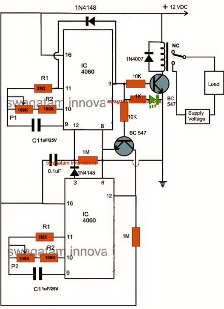
The circuit of the proposed incubator egg timer and optimizer is given below:P1 should be adjusted for the long 8 hour duration and P2 for the short 3 seconds duration.
Circuit simulation:
Looking at the circuit diagram we can see that it consists of two identical IC 4060 stages which are coupled across each other for implementing the proposed actions.
The upper timer stage is intended for producing long time intervals and therefore its output is taken from pin #3, while the lower IC generates smaller time intervals and so its pin #15 is chosen as the output.
When power is switched ON the following things happen with the circuit:
The 0.1uF capacitor resets the upper IC so that it can start counting, during this period its pin #3 is at logic low which keeps the relay driver stage switched OFF, also the lower BC547 is kept disabled, which keeps pin #12 of the lower IC at high logic which in turn renders the lower IC inactive.
After the predetermined period is lapsed, pin #3 of the upper IC goes high, this switches ON the relay driver stage and also the lower IC pin #12 gets reset, this toggles the lower IC into counting mode.
After the predetermined period, pin #15 of the lower IC becomes high, which sends a logic high to the reset pin #12 of the upper IC, resetting it back to its original position......the cycle repeats, and goes on repeating as long as power is available.
The lower section can be upgraded for generating higher time intervals at par with the upper section by replacing pin15 with pin3 as already done in the diagram below.
The relay contacts are wired up to the motor for shuffling the egg orientation.
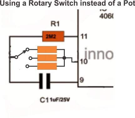
Using Rotary Switch for Adjusting the Time intervals
If you find adjusting the pot difficult and time consuming, you could easily replace them (P1, P2) with rotary switches as shown below. The involved could be also easily calculated with some quick and experimentation:



Questions & Answers
Hi Chandadna,
The timing can be extended by increasing the values of the Pots and C1s…..you can try 1M pot instead of 100k and put a couple of more 1uF caps parallel to the existing ones, this will provide you with a higher timing range.
Dear Chandana,
Please provide information about your requirement specifications, I'll try to work it out accordingly.
Hi Sam,
Are you looking for the incubator thermostat circuit?
Here it is:
https://www.homemade-circuits.com/2011/12/how-to-build-simple-electronic.html
Hi Aponso,
I'll try to design a simple circuit and let you know soon.
It may take a little time, but you will surely get it.
Done, It's published here:
https://www.homemade-circuits.com/2013/09/simple-electronic-load-controller-elc.html
Hii sir… what amp rate should I supply this circuit??
Hi Srishan, use a regulated 12V power supply, Amp rating is not crucial but it should not be less than 100mA
Awesome….thank you sir…..
And I made the incubator temperature circuit and it works perfect… Thank you for it 😀
you are welcome Srishan.
Dear bro… I'm a completely new hobbyist for electrical projects…. and I'm gonna make an incubator for my pigeons and ur circuit of auto egg turner is just awsm…. but as because i'm so new here i got the positive power connection but witch is the negative power connection pls mention it for me… and i completed this circuit on a breed board but when i connect with 12volts with positive and earth connection my lower ic gets hot and the heat keeps increasing …. so pls tell me why this is happening witch will be so great full to you…Thanks, Tanvir
Dear Bro, with reference to the following diagram, the line which is connected with pin4 of the IC is the negative line and must be connected with the negative of the 12V supply.
The IC should not become hot….there could be some major fault in your circuit connections, please check it properly.
https://www.homemade-circuits.com/2011/12/how-to-build-simple-electronic.html
Hallow bro I'm so grateful to u for ur reply its now working well.. 🙂 and now i need to know also about egg turner circuit, witch one is the negative port to connect with power ? is these 4060 ics are cmos or another ?unluckily in this circuit my lower 4060 ic is also getting hot and the heat keeps increasing, wht could be the problem? and what is the procedure to make caps parallel? if u pls explain I'll be grateful, and i am making an incubator by ur circuit for my pigeon eggs, for wht humidity is so important, so can u pls provide us a programmable humidistat or hugrosta's easy and simple circuit diagram witch can produce humidity to fixed level in incubator chamber by an watering source? coz it will make the incubator perfect and complete. Thanks a lot… 😀
That's great Bro!
In the above programmable timer circuit, the line which shows an "earth" sign is the negative line.
Yes, the IC4060 is a CMOS IC.
The IC will become hot under two conditions, if the supply voltage goes above 16V or/and if its outputs are shorted, so you would want to check for those….
I will surely post a simple programmable humidity controller soon in this blog and let you know.
…….caps can be made parallel simply by joining their leads together…..for example you can see the following diagram which shows caps connected in parallel:
https://www.homemade-circuits.com/2012/08/high-current-transformerless-power.html
Thats just great bro…:) I'll be waiting for Ur programmable humidity controller eagerly witch will make my incubator completed as early as u give me the circuit and pls draw the circuit with details of ports, connections and component's picture so that we as a new comer can understand that easily and enjoy Ur help ,, I'll checkout the fault and of timer circuit and let u know… 🙂 Thank u so much brother,, R U Bengali ?… 🙂
It's my pleasure bro! I'll try to post it soon with all the necessary details, yes I'm bengali.
taholeto ami lucky akjon expert vi pelam obossoi onek kichu sikhte parbo…isn't it?… 🙂
surely Mr.green, feel free share your thoughts here…. by the way I have published the humidity controller circuit you requested for, you can see it here:
https://www.homemade-circuits.com/2014/03/programmable-humidity-controller-circuit.html
Dear bro thanks a lot for the circuit of humidity controller,, I'll make it but I'm so disappointed that i couldn't collect caps 1uF/25volt non polar or .47 uF non polar so that i couldn't make the egg turner circuit… and by the way, my name is Tanvir… 🙂 Thanks
Dear Tanvir, no issues you can other values also for the capacitor, it should be non-polar that's all….for increasing time delays you can increase P2/R2 values to any desired higher levels.
Dear Swagatam,
Is it possible to identify the switching time interval of the relay by seeing the the blinking rate of the LED's connected across pin 15 and ground if both the ics. i have used 1u 63v capacitor is there any change in the time interval if the volt rating of the capacitor increases.
Regards,
Liju
Dear Liju,
yes surely that's possible…..all the outputs switch at a particular pin order sequence where pin3 produces the slowest frequency and pin7 the highest….the order increments at the rate of 2x.
you can refer to the following post for more info on this:
https://www.homemade-circuits.com/2011/12/how-to-understand-ic-4060-pin-outs.html
Hi bro,
its tanvir again, i collected some 1 uF and .1 uF non poller caps but there volt value is different and still the circuit is not working properly, i am sending capacitor's pics and 100 K verriable resistors and its connected pins picture also to ur "homemadecircuits@gmail.com" e-mail add,
pls see it and tell me that are these correct components? Now the main thing is i build the circuit and when i'm connecting it with power the 400 ohms SPDT relay sounds energize and keeps ticking after3 seconds for 1.20 minuets then it stops ticking and restart ticking after 1.20 minuets again and it continues, so what the hell is happening and what is wrong i've done? and what is the fault and solution pls elaborate details with pics my dear brother because i cant do anything until i make this device, Thanks bro… 🙂
Hi bro, something could be terribly wrong with the connections or the parts, because the circuit should start working correctly as soon as it's switched ON…I have tested it.
try 1M pot in place of 100k, this will provide a wider range of time selection.
please refer to the following post, it has the same design but with little modifications, could help you troubleshoot the issue.
https://www.homemade-circuits.com/2012/04/how-to-make-simple-programmable-timer.html
Dear Swagatam,
Thanks for your reply.I would like to know, what changes i need to make in the above timer circuit to get the relay to be switched ON in one hour interval and cut off after 10-15 seconds.
Regards,
Liju
Dear Liju,
you will have to do it with some trial and error.
You can do it by initially replacing R2, P1 with a 33k fixed resistor and see what time delay it produces, if it gives say a 50 seconds delay would mean that a 66k would produce 100 seconds delay and so on……the response would be very linear.
i do believe in ur circuit but don't know why i dont have confidence on my parts so that i sent some pics of my parts to ur "homemadecircuits@gmail.com" this e-mail address, did u get it if so then pls reply me that those parts are correct, so I'll have confidence again to rebuild it … , I'm using 400 ohms SPDT relay, is this correct ? … thanks bro .. 🙂
Bro, i have checked your email….all the parts are OK.
I have updated the above diagram with some modifications please do as per the new diagram, i am sure you'll succeed.
dear sir,
according to the description, its told like, pin 15 of lower ic should be used for attaining 3 secs interval.. but when i made a close look of the diagram, no connection are there in lower ic's #15.
how can be this justified..???
dear Arshad, I'll make the necessary corrections soon….pin15 was later replaced by pin3 so that the lower section could also become capable of generating larger time intervals, at par with the upper section.
Thanks ya..
Hallo brother,
It seems that i'm such an unlucky person for this device, coz i made it but it's not working, at first i made it and connect it with power and both of the led and relay turns on and doesn't response with pots,
brother i know there must be a connection problem but the thing is where the connection problem can be if u pls mention some of the miss connections or problems for this troubles i can check it and sort it out… pls brother mention some problems witch could be with this. and is the 4060 ic are sensitive.? should i forget to built it bro?… 🙂
hello bro,
i think you should rebuild it and this time make and test the stages separately.
First build the upper stage and check it's response and then go for the lower stage.
Both the stages are actually identical, simply cascaded to work in tandem.
The lines connected with the earth symbol must join with the negative of the supply.
The positive supply must not exceed 15V.
No, 4060 is not at all sensitive or vulnerable, unless connected wrongly.
Hey brother, its tanvir again , u know wht? i was so frustrated that i couldn't build it, but last night i tried once to build it and and just for interest i connect a led to pin 7 of upper ic via 1k resistor to negative point and i see it is blinking i got excited and keep wiating wht happens and after sometime i see the relay activates… but now there is a problem ,, when i connect a motor with the relay than power the device than the relay activate and turns off instantly …. but when is the motor disconnected the device works properly .. wht could be the problem ? pls mention the problem with details solution so that i can sort it out… thanks brother… 🙂 i am using 400 ohms SPDT relay .. but wht is the correct relay should be??? pls elaborate..
congrats bro, keep it up.
is you motor dropping the supply voltage while switching ON? in that case you will need to use a higher amp supply input.
you can also try putting a 220uF/25V or bigger capacitor parallel to the motor wires and check the response.
One more thing i forgot to say i build the previous one not this one… will it be of with it ?
the diode across pin3/pin11 in the above circuit is crucial, it must be included.
Dear brother ,
i connected the led with pin 5 maybe that was the problem now i connected the led with pin 15 and the motor is working properly..now give me some safety instruction for the device and should i connect any capacitor with the motor's pins? coz i saw it in a remote controlled toy car. and is it possible to add variable resistor instead of 100 k resistors so that we can change the resistance from 10 to 100 k when we need to ? if so wht power of resistor should we use and how to connect it ? thanks … 🙂
Dear brother you can connect a 100uF/25V capacitor parallel with the motor wires, and also a 0.1uF directly across the IC supply pins, a pot can be used for setting the time intervals as shown in the diagram.
brother , how to set a nob with the variable resistors and how to measure the interval periods of this device , coz its really tough to wait for long to measure the times of the divice.. 🙂
this you will have to do with some trial and error, make a dial behind the pot knob and mark the minimum, center, and maximum delays obtained across the entire dial radius, once this are fixed the intermediate delays can be marked simply by graduating the dial linearly.
ok bro i'll do it,, now pls give me some safety tips of this device and should i connect any capacitor with the motor for its safety and perfect output…
you can connect any electrolytic capacitor parallel to the motor wires
and bro .. how to supply to this device perfect 12 volt by connecting direct to 220dc volt without transformer… Thanks
bro you will 12V ac/DC adapter for this….what were you using for so long, a battery??
dear bro,
thanks for the suggestions, but can u pls show the diagram of 0.1 uf caps connected with the ic pins… or witch number pins will be connected with the cap? and unfortunately i couldn't find any 25v caps here, i'm using higher volts caps, will it harm the device or its activity ? Thanks
bro, connect it directly with the pins16 and pin8 of the ICs…………it surprises me how you are not able to find the supply pins of the IC which are clearly shown in the diagram and which are already connected in your prototype??? higher voltage caps will be fine…no issues.
and i want to make it digital,, so can u pls help me out ? can u pls draw this device's diagram with a seven segment led or lcd display?
presently don't think about it bro:) when you are not able to make such a simple circuit which is shown above, how would you be able to make a complex digital circuit integration with the above.
thanks bro, it happened as i told u before, that i am totally new in this site,,, and i appreciate ur comments ,, as because u are now my honorable teacher.. Thanks
you are welcome bro, I'll try my best to help you out in the field.
dear sir what function.of led in circuit. i made this circuit unfortunely the led not lighting when i turn on the power. can u explain. thanks
dear Rizsha,
red indicates upper timer is counting, green indicates the lower is counting.
if none of them are lighting means something's wrong with your circuit.
Hi sir..can I use this.circuit for a hydroponic irrigation system? All I want to do is to run a mini water pump of 12v every 3 hours for 20 mins….. will this circuit do the needful???
Thank you
Hi Srishan,
yes it can be used and will work perfectly, just make sure the relay contacts are rated according to the load amps.
Thank you so much sir…..:D
dear sir mean led willl light on when 12v switch on and green led will on when motor turn on,rite?
yes that's right.
dear sir, led blink or not if the circuit in operation
no blink, only light
hi sir could you please guide me to solve my little problem? i have tested the circuit on project board and it worked but i couldn't set the time interval to be different, i upgraded the lower caps and resistor to be higher but it wasn't changing the time interval. the relay was only on about 3 minutes and then of about 3 minutes again. i need 20 seconds on and 2-3 hours off. thanks in advance
Hi rood, something's not right in your circuit for sure.
connect an LED with a series 1k resistor across pin7 and ground of the lower 4060 IC. (cathode to ground)
As soon as the red led shuts off this LED should start flashing indicating that the lower stage has been activated.
If you don't see this response could mean an incorrect wiring or faulty components.
you right sir i just made an error in wiring the components. i now have to tell you that the circuit is working properly now it's great. i followed your instruction and replaced the upper pots with 1m pots and connected the lower 1N4148 diode to pin 6. now i have 1 hour off and 15 seconds on. now i'd like to increase the upper timer to be 3 hours. i like your circuit thank you very much sir.
that's great Rood, you can increase the upper IC timing by connecting more number of capacitors in parallel with C1, all should be strictly non-polar type.
Sir I did the circuit but I only need 20 mins on the upper ic… hw can I get it done? And I couldn't find 1uf/25v caps bt I only got 1uf/1000v non polor. Will this make a problem? And does the 0.1uf cap has a voltage rating?
Srishan,
1uF/1000v will also work, use a 1M pot for the upper P1 and set it to get the required timing by some trial and error.
0.1uF can be a 50V disc capacitor.
Dear sir, I made the circuit and I'm so happy that my circuit work fine more than I expected…I replaced the pots with 1megs and in order to check the blink rates of both the ics I used two leds on both 7 pins of the ics with 1k resister,
And to my dear friend who has commented on this circuit. Plzz take a bit of time to carefully study the diagram and make it… if you do exactly do as said believe me it works 100%
And once again thank you so much sir 😀
That's great Srishan, congrats to you, I appreciate your hard work, and dedication.
Thank you sir…. 😀
Hi i made this circuit but i used 1uf electrolite caopacitor but it not works? because it should be NP? when i apply power relay activate? is it activate or not?
Hi, even with a electrolytic capacitor the relay should NOT activate on power switch ON, there could be some other fault in your circuit.
hi swagatam, i tried to build the circuit, when the power applied the relay activate, the red LED illuminate, the green LED off, On pin #7 I connected 1k resistor and LED to the ground on both IC`s, they are both blinking, after 30 mins the red LED Off and the green LED On 30 seconds, but noting's happen on my Relay, after 30 seconds, the green LED Off the red LED On, but the LED on upper IC pin #7 is not blinking, the lower IC still blinking.
I used 104 cap ceramic type and 1uf/50v cap non polar similar to this -> us.100y.com.tw/product_jpg_original/A011025.jpg, is their something's wrong with my circuit?
Hi unknown, when power is applied the relay should NOT activate….may be the circuit is getting latched at the onset itself….try increasing the 0.1uF at pin12 of the upper IC to 0.22uF or higher and check the response.
I rebuild the circuit, when power is applied, RED On, Green Off, pin #7 Blinking, Relay was not activated, after 30 mins RED Off, Green On, pin #7 stop blinking, but still the Relay was not activated,. i replace all my caps 104, 105 to Mylar type capacitor
It indicates that the relay transistor may be faulty or not connected correctly or may be the base 10K ersistor is faulty.
i buy new of components 🙂
what if i only want 2 hour On and 2 hours Off? i will remove the Pin #3 and 1N4148, Pin #8, Pin #12, 1M, Pin #16, and BC547 and it base resistor?
for equal time durations, you can completely eliminate the lower IC stage along with the lower BC547…not the upper BC547 stage…
The 1N4148 will also need to be removed for obtaining a sustained ON/OFF response from the IC.
Thank you very much Swagatam! IT WORKS! can I remove P1 and replace R2 with my desired resistor value to get my desired timing? Im a programmer swagatam and no background in electonics, thank you very much for guiding me,.. 🙂 what is the use of 1N4007 diode in relay? if i have multiple relay do i need to put diode? can i add fuse or any safety features?
my next project is your Solar Battery Charger, moving to the next level hahaha,..
You are welcome Unknown! yes P1 may be replaced with a suitable resistor for enabling the intended fixed oscillation periods
The 1N4007 will protect the driver transistor from relay coil back EMFs, for multiple relays in parallel a single 1N4007 would be sufficient, individual diodes may not be required. However the transistor may need an upgrade if the relay count is over 2. You can try a 2N2222 or a 8050 in place of the shown BC547.
A fuse is not crucial and may not be required for such low voltage DC operations…
wish you all the best for your next project…keep it up:)
ic, its for back EMFs, thank you very swagatam!
Dear bro,
I made the display driver its working great,, and I'm so happy for it, but bro is it possible at a display witch will show the set time when I'll turn the pots? Thanks
Dear bro, which circuit are you referring to? i can't remember, please comment under the same article..
The circuit was but my requirement was like when I'll turn the pots, led display will show the times like if set the timer for 4hours and relay for 5 mints these times will appear on the led display… is it possible my brother??
It looks difficult with discrete components, sorry bro not possible because display circuits are not easy to design using ordinary components.
Hi bro,
its tanvir again, ur great device i made last time was working so good for long but suddenly i see its wrkin wrng, whn i power it up relay activates, and relay transistor bc547 gets extreemly heated. I changed the trans i changed the 10k resis, even changed the 4060 upper ic, but it still hving the same problem, i tried a lot to solve the probs bt couldnt do anything, so can u please help me to solve it? Thanks
Hi Bro,unless the input voltage is increased above 18V or there's some short circuit in the circuit, it's unlikely to become hot or malfunction, or may be the ICs you have used are not of good quality.
Try Using a 12V AC/DC SMPS adapter instead of transformer.
Hi sir,
Im a new hobbiest, i was looking for a timer for long and i found it in ur blog, but after i made it im having some common probs, that is when i power it up relay activates and red led on, after some time grenn led turns on but red does not fully off ,it deems but keeps on and no change to relay, im using 10k for R2 and 10 k pot for p1 for both ic, my ics ar new and good quality, i made it several time bt problem is always same, and there is no probs wit any resistor,, sir pleaae tell me what can i do?
Hi Riya,
Your circuit may not be correctly assembled, because on power switch ON the relay should not activate. The relay will activate only after the upper IC time has elapsed, and deactivate when the lower IC time has elapsed.
something is wrong in your circuit, may be the transistors are not connected correctly.
On powering the REd LED will be ON, never both.
Dear sir
Here how i built ur circuit, at first i built the upper ic option and when i power on it was working 100 percent ok, after that i attach the liwer ic option nut after that i connect a led across negative and upper ic pin 7, the led blinks as well but nothing happen with relay or liwer ic ,i added abrand new ic for lower portion, but still works nothing, i waited for long long time but result is same,, is the problem with 4148 diod? Or how can i solve it ? My lower ic ppt is 10k and r2 is 10k where upper on is 100ksl s, thanks.
Dear Riya, you must do exactly as given in the diagram…the resistors should be 100k for the pot and 2M2 for R1….the diodes are OK and must be included…connect LEDs in series with the transistor bases, that is in between base and the 10K resistor of both BC547s….the LED will indicate when and how the transistors are conducting in sequence or if there is any mistake in the IC function..
Hallo sir,
Im having a prob, at first i made the circuit without led and keep it for aomedays and it was working very good, after somedays i try to add the led but when i power it on relay activates with red led, but when i disconnect the red led the device works good again, what could be tje problem sir? Thanka
hello riya,
try a higher value series resistor with the red LED, use a 10K or 15K resistor and check the response.
Hi sir can i use 12 V transformerless adaptor to be the power supply to this circuit? I have made the adaptor, but im not sure about amp issue, please help,,
Regards
Hi Harvest, the current is not important, but make sure the voltage is strictly within 15V, then it can be safe to use.
I use 12 volt dc transformerless power supply, when I first operated it, the red led is on but its dreary i think because its current input low, after that i have been waiting long and nothing happened, the red led still on. Whats going on sir? I use 2M for R1
check with a 12V AC/DC adapter for confirming the circuit operations, and anyway a transformeless power supply might not work, it could produce wrong results and might not be capable of the driving the relay….
2M is fine for R1
C1 must be non-polar
hi sir i use adaptor 12 v 1 a. Nothing diffrence with the firs time, led on and dreary, when i connected led across pin 16 and ground via 1 k resistor, this led on and brightly. When i connected led across pin 15 and ground via 1k resistor nothing happened led still off, would you like to help me this issue,,
Harvest, initially the red LED should be ON brightly, and when the time elapses for the upper IC, red LED should shut off and green LED should illuminate….if connected at pin16 or pin 15 the LED should flash
I think something's not right with your connections or the circuit.
thanks sir, I almost success to built it, when I connected led across pin 7 via 1 k resistor the led blink fast, and also pin 15 also blink and slowly but the P1 cannot change blink speed, the other hand, the lower IC do not blink. whats going on, I have drown pcb lay out. please check sir, maybe something wrong on the connection that I dont know.
https://drive.google.com/open?id=0BwFU-bL_-g3deDRxU1QtVGdTYzdvMU1xWEtaZ1VCcVplOGpr