This interesting furnace vent controller circuit was designed and submitted to me for publication by a dedicated reader of this blog and a keen electronic enthusiast Mr. August Peterson. I am extremely thankful to Mr. August for his very useful and generous contribution to this site.
Here's the email sent by him, with the technical specifications of the design:
Overview
Hi Swagatam, Thank you for the tremendous work that you do to help people and I have learned a lot from your articles.
I had a project to automatically open and close the furnace vent to maintain a reasonably constant room temperature but could not find a circuit without relays so I developed the attached circuit which you are welcome to share with anyone that is interested.
It may not be perfect but this is my hobby not my profession, and I use mostly salvaged parts.
Regards from August Peterson.
How it Works
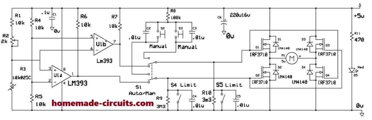
S1 switches the controller from automatic to manual mode if required. R4 & R5 form a potential divider & supply a reference voltage of 1/2 of the power supply voltage to the comparators U1#5 & U1#2 (2.5v). A set point voltage is derived from the voltage divider R1, R2, R3.
R2 is for adjusting the set point. When the set point to U1#3 & U1#6 is above the reference voltage at U1#5 & U1#2 due to a cool R3 (NTC) then U1#1 is positive (5v) through R6 & U1#7 is close to 0v.
U1#1 positive is applied to Q2#G & Q3#G & so they conduct.Q3#S supplies M1 with a positive & Q2#D supplies M1 with 0v (Gnd) and M1 rotates until a mechanical link closes S4 which stops the motor M1.
The air vent would now be open and supplying warm air to the room.
When R3 warms up, it’s resistance reduces which pulls the voltage at U1#3 &U1#6 lower than the reference voltage.
When U1#6 is lower than the reference voltage on U1#5 then U1#7 will become positive through R7.
The positive from U1#7 is applied to Q1#G & Q4G so they now conduct.
Q1#S supplies M1 with a positive (5v) & Q4#D supplies M1 with 0v (Gnd), the motor now rotates in the opposite direction to before until a mechanical link on the vent closes S5 which stops the motor.
S1 disconnects the comparitors from the circuit and connects S2 & S3 to the motor drive circuit.
R8 supplies positive to S2 &S3 to bias the Mosfets.
Pressing either of the switches will open or close the vent which can be stopped in any position, unlike when being driven by the comparators in automatic mode, the vent will only stop at the open limit or the closed limit.


Need Help? Please Leave a Comment! We value your input—Kindly keep it relevant to the above topic!