Video Demonstration of the Crescendo Amplifier
The mini crescendo 100 watt transistorized amplifier circuit explained here was built and tested by me and am extremely pleased by its performance and also its ruggedness as far as maintenance and handling is concerned.
Amplifier Class
Basically, the entire configuration is a symmetrical class A amplifier incorporating an input filter stage, an intermediate driver stage and a powerful symmetrical output stage consisting of the versatile 2N3055 power transistors.
The circuit efficiently drives a 100 watt 4 Ohms speaker with inputs derived from any audio source like a cell phone or DVD player etc.
Before you learn how to build this interesting and useful 100 watt amplifier circuit using 2N3055 transistors, a prior understanding of the involved circuit configuration would be very handy, let’s begin the explanation with the following points:
Circuit Operation
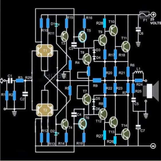
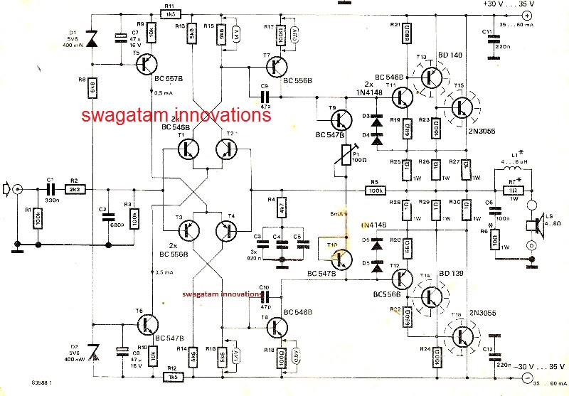
A quick glance at the given circuit diagram makes us conclude that the output configuration is not symmetrical, since the transistors T15 and T16 are both NPN types.
The input stage of the circuit begins or initiates with a symmetrical differential preamplifier stage consisting of the transistors T1, T2 and T3, T4.
T5 and T6 are positioned as the current sources which are further extended as the driver stage consisting of the transistors T7 and T8.
However a closer inspection tells us that of course the wiring is symmetrical, having the transistors T11, T13, T15 at the upper section acting like special booster transistor package.
Similarly the lower section also employs identical super booster stage consisting of the transistors T12, T14 and T16.
The above two sections are perfectly complementary to each other, with reference to the diagram which indicates their emitters being terminated to a common point through the resistors R25 to R27 and via R28 to R30, this effectively that the wiring is exclusively symmetrical by nature.
The output stage is able to produce a massive 200,000 times amplification factor with comparatively very low quiescent current drain.
The quiescent can be set by the adjusting the preset P1.
Due to a non critical nature of the circuit, the entire project can be easily built over a general purpose PCB, however the layout of the components or rather the placement and the ratio of the distance of the components must be kept as identical as possible to the layout of the circuit diagram.
Though a common heatsink may be used for the entire set of the output devices, I personally used separate individual heatsinks for each of the transistors.
This saved me from the headache of using the cumbersome and low efficient mica isolation kit between the transistors.
The inductor is kept for improving the dynamic nature of the circuit. It is built by winding 20 turns of super enameled copper wire over the 1 Ohms resistor itself.
The wire is selected to be close to 1mm in thickness.
Though not absolutely necessary, for better thermal stability the transistors T9 and T11 and also T10 and T12 should be glued together, preferably by attaching the respective pairs face to face.
The quiescent current should be ideally set to 50 mA through the following initial procedure:
How to Set Quiescent Current
1) Remove the speakers, and short the input terminals (across R1),
2) Connect a DMM set at current range in series with the positive of the power supply to the circuit,
3) Next adjust the preset such that the meter reads an input of 50mA, that’s all, the amplifier’s quiescent current is set and now the connections may be restored for the normal operations of the system.
Power Supply Circuit
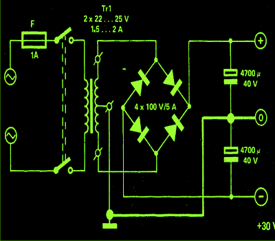
The power supply circuit is also shown along side and as can be seen there’s nothing special about it and may be built using the shown ordinary sets of components.
Parts List of 100 watt amplifier circuit (sh0wn below)
- R1 = 430 K,
- R2 = 47K,
- R3 = 330 Ohms,
- R4, R5 = 12 K ,
- R6, R7, R20, R21, R22, R23, R24 = 1 Ohm, 3 Watt, Wire Wound Type,
- R8, R17 = 68 Ohms,
- R9 = 100 K, R10, R11, R12, R13 = 5K6,
- R14, R15 = 12 K,
- R16, R19 = 100 Ohms,
- R25 = 10 Ohms / 2 Watts,
- P1 = 100 Ohms Preset, Linear,
- C1 = 1 µF / 25V,
- C2 = 1 n, CERAMIC,
- C3, C4 = 100PfC5 = 100 nF,
- C6, C7 = 1000 uF / 35 V,
- L1 = 20 turns of enameled 1mm copper wire over R24,
- D1, D2 = RED LED 5mm, All other diodes are = 1N4148,
- T1 = Matching BC546 pair,
- T2 = Matching BC556 pair,
- T3 = BC 557B,
- T4, T7, T8 = BC 547B,
- T5, T12 = BC 556B,
- T6, T9 = BC 546B,
- T10 = BD 140,
- T13 = BD 139,
- T11, T14 = 2N 3055
- General Purpose PCB,
- All the transistors T10, T13, T11 and T14 ae mounted on suitable heatsinks
The original design, (courtesy - elektor electronics)
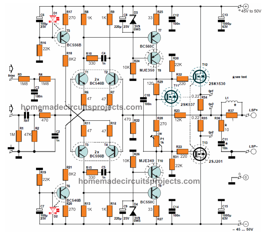
The MOSFET version of the above design can be witnessed in the below given image:
For the complete construction details, please refer to the following link:
Mini Crescendo pdf with PCB and protection circuits




Questions & Answers
Sir,
I want to made this audio amplifier circuit. But in the amplifier circuit you show the 25V supply and in power supply circuit there is 30V.
What is co-relation between them. secondly, I want to known the rating of center tap transformer you have used.
Sudesh
After rectification the voltage may rise upto 30V, but it won't be a problem because the amplifier can handle upto 40V
Thanks for the help Lancy, keep it up mate:)
do you have any sub woofer pre amplifier circuit for this power amp if you have mean's wiil you please send me (kanagarajbe114@gmail.com)
You can use the following circuit, just add a low pass filter at the input of the amp:
https://www.homemade-circuits.com/2012/04/how-to-make-simplest-100-watt-mosfet.html
Thank you sir,and i want single supply transistor power amplifier circuit I have o-24 transformer 5amps
I am sorry kanagaraj, I do not have any such circuit presently in my blog, I will try to update it if possible soon.
sir hoe to increase left right bass depth without using tone controles (only using pre amplifier) if you have any circuit like that give me
You can replace the preamplifier with this circuit, it will work as both preamp and low pass filter:
https://www.homemade-circuits.com/2013/06/make-this-low-pass-filter-circuit-for.html
sir i want one automatic battery charging circuit (12v) i want that circuit automatically sence low battery and start charging and cut the charging when the battery is full
Hi Kanagaraj, You can make this circuit:
https://www.homemade-circuits.com/2012/02/how-to-build-automatic-6-volt-12-volt.html
replace the feedback 1K resistor with 100k pot and remove the series 1N4148 diode.
sir hoe to cut below 80HZ in low pass filter circuit
By carefully adjusting the 22k presets.
sir i want buffercircuit & bass boost circuit using op amp
what is the different between digital ground and analog ground and how to joint these two grounds
it's a big explanation, cannot provide it here….these grounds are intended for providing discrete paths for analogue and digital signals, they should not be joined.
Don't use passive filters, use active filters as it will enhance the effects rather than deteriorating.
You can use the circuit IC2A/B section of the circuit shown in this link, use it in between your amp and music input:
https://www.homemade-circuits.com/2012/01/how-to-make-your-own-active.html
That's great support Lancy, Thanks very much.
Would it be okay if i use all the smd component instead of through hole component ,can my circuit behave diffrently under smd components ????
Please answer ……
yes you can use SMD, the circuit will work perfectly with them too, no issues.
there are 2 types of 3055 transistor. first one is 2N3055 and other one is TIP3055. TIP3055 is a big transistor. 2N3055 is like a normal transistor. which one is good for this amplifier. I cant understand the L1 . How can i make it in home. I'm stuck in this plese reply me soon.
Both the transistor types are almost identical with their specifications, only the package is different.
You can use any of these as per your convenience….I have updated L1 data in the parts list.
can you post a completed circuit with all parts
can you send PCB soft copy to my mail:- manujamicro1@gmail.com
please some one send me the PCB soft copy. my email- manujamicro1@gmail.com
The value of L1 has been updated in the parts list.
i00.i.aliimg.com/photo/v0/309836240/TIP3055_Power_NPN_Transistors_ST.jpg
img.bhs4.com/fa/d/fadf150f65b8acbacfb586f7ab802d0a80dced83_large.jpg
checkout this links and tell me the witch transistor is good for this circuit. please some one send me the PCB soft copy. upload that and give me the download link.
as mentioned in my previous comment, both the transistors are good and rated almost equally, it depends which one you prefer as per your convenience.
i00.i.aliimg.com/photo/v0/309836240/TIP3055_Power_NPN_Transistors_ST.jpg
then can I use this transister
yes you can use them, be sure to add large finned heatsinks to them
is there a good quality bass in this amplifire.
please tell me
No, it does not include bass control, you will have to add it externally
no no I mean the sound. can i get a good bass sound from this
you can get god bass only after including a bass/treble circuit at the above amplifier input
what is the correct swg for the L1 coil
20SWG
do you have is there any subwoofer circuit schematic. if you have please send me. Because i want a good bass. thats what i like
I'll try to include it soon in this blog and give you the link….
in our city there was a young man. he makes subwoofers in home and sell them. but i dont have money to buy that. he has many types of subwoofers. like 5.1 , 2.1 , 7.1. now he is not here. but i want to make one. quality bass sound subwoofer circuit diagram. thats what i need. if you have that send me. i will give my email. thankz
presently i do not have it, i'll try to post in soon and let you know.
ow do you have above amplifire pcb diagrame?
sorry, presently the pcb design is not there with me…
I have seen your link, yes you can use it with the above circuit
…and please do not include external links, i'll just keep deleting them.
how can i contact you for a personal matter immediatly pleaseeeeeeeeeeee
This looks like a very nice amplifier, thanks for the detailed schematic and items list! I have just ordered the components and I'm excited to get started!
I have one questin though – I can't seem to figure out the recommended power suppy voltage/current. I'm confused with the shchematic sayin "Tr1, 2 x 25" Do I need a dual transformer, or?
If I only need one, will 30 Volts at 5 Ampere be suficient? Can less do it?
Im planning on winding my own transformer, so no need for "standard values" 🙂
Thank you!
The transformer needs to be a center tap transformer, that is with two sets of winding on the secondary, rated as 24-0-24V at 2amps or more.
you can use a transformer rated at 30-0-30V/2amps also.
Thank you very much. If I want to make 2 of these amplifiers, one for each channel, can i just make two identical amps and ground them to the same "0" on the transformer (offcourse with twice the current), or do I need 2 seperate center-tapped windings with their own respective "ground/0"
separate power supplies won't be required, you can use the same supply, just by making the grounds common…