Video Demonstration of the Crescendo Amplifier
The mini crescendo 100 watt transistorized amplifier circuit explained here was built and tested by me and am extremely pleased by its performance and also its ruggedness as far as maintenance and handling is concerned.
Amplifier Class
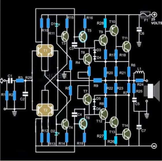
Basically, the entire configuration is a symmetrical class A amplifier incorporating an input filter stage, an intermediate driver stage and a powerful symmetrical output stage consisting of the versatile 2N3055 power transistors.
The circuit efficiently drives a 100 watt 4 Ohms speaker with inputs derived from any audio source like a cell phone or DVD player etc.
Before you learn how to build this interesting and useful 100 watt amplifier circuit using 2N3055 transistors, a prior understanding of the involved circuit configuration would be very handy, let’s begin the explanation with the following points:
Circuit Operation
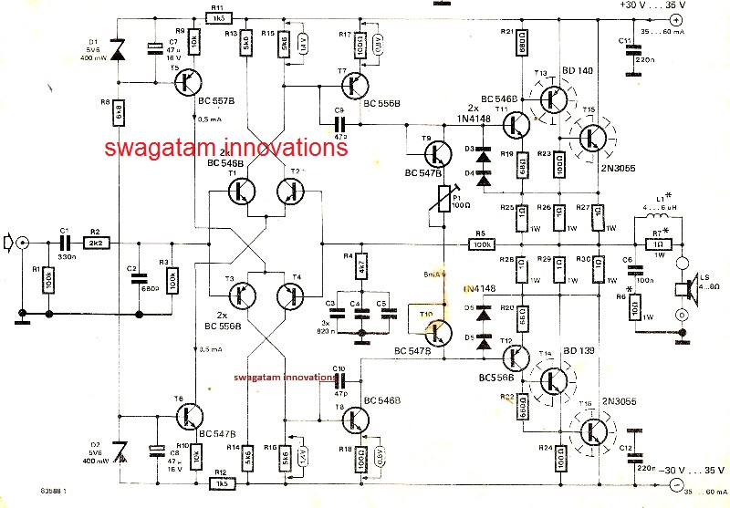
A quick glance at the given circuit diagram makes us conclude that the output configuration is not symmetrical, since the transistors T15 and T16 are both NPN types.
The input stage of the circuit begins or initiates with a symmetrical differential preamplifier stage consisting of the transistors T1, T2 and T3, T4.
T5 and T6 are positioned as the current sources which are further extended as the driver stage consisting of the transistors T7 and T8.
However a closer inspection tells us that of course the wiring is symmetrical, having the transistors T11, T13, T15 at the upper section acting like special booster transistor package.
Similarly the lower section also employs identical super booster stage consisting of the transistors T12, T14 and T16.
The above two sections are perfectly complementary to each other, with reference to the diagram which indicates their emitters being terminated to a common point through the resistors R25 to R27 and via R28 to R30, this effectively that the wiring is exclusively symmetrical by nature.
The output stage is able to produce a massive 200,000 times amplification factor with comparatively very low quiescent current drain.
The quiescent can be set by the adjusting the preset P1.
Due to a non critical nature of the circuit, the entire project can be easily built over a general purpose PCB, however the layout of the components or rather the placement and the ratio of the distance of the components must be kept as identical as possible to the layout of the circuit diagram.
Though a common heatsink may be used for the entire set of the output devices, I personally used separate individual heatsinks for each of the transistors.
This saved me from the headache of using the cumbersome and low efficient mica isolation kit between the transistors.
The inductor is kept for improving the dynamic nature of the circuit. It is built by winding 20 turns of super enameled copper wire over the 1 Ohms resistor itself.
The wire is selected to be close to 1mm in thickness.
Though not absolutely necessary, for better thermal stability the transistors T9 and T11 and also T10 and T12 should be glued together, preferably by attaching the respective pairs face to face.
The quiescent current should be ideally set to 50 mA through the following initial procedure:
How to Set Quiescent Current
1) Remove the speakers, and short the input terminals (across R1),
2) Connect a DMM set at current range in series with the positive of the power supply to the circuit,
3) Next adjust the preset such that the meter reads an input of 50mA, that’s all, the amplifier’s quiescent current is set and now the connections may be restored for the normal operations of the system.
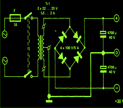
Power Supply Circuit
The power supply circuit is also shown along side and as can be seen there’s nothing special about it and may be built using the shown ordinary sets of components.
Parts List of 100 watt amplifier circuit (sh0wn below)
- R1 = 430 K,
- R2 = 47K,
- R3 = 330 Ohms,
- R4, R5 = 12 K ,
- R6, R7, R20, R21, R22, R23, R24 = 1 Ohm, 3 Watt, Wire Wound Type,
- R8, R17 = 68 Ohms,
- R9 = 100 K, R10, R11, R12, R13 = 5K6,
- R14, R15 = 12 K,
- R16, R19 = 100 Ohms,
- R25 = 10 Ohms / 2 Watts,
- P1 = 100 Ohms Preset, Linear,
- C1 = 1 µF / 25V,
- C2 = 1 n, CERAMIC,
- C3, C4 = 100PfC5 = 100 nF,
- C6, C7 = 1000 uF / 35 V,
- L1 = 20 turns of enameled 1mm copper wire over R24,
- D1, D2 = RED LED 5mm, All other diodes are = 1N4148,
- T1 = Matching BC546 pair,
- T2 = Matching BC556 pair,
- T3 = BC 557B,
- T4, T7, T8 = BC 547B,
- T5, T12 = BC 556B,
- T6, T9 = BC 546B,
- T10 = BD 140,
- T13 = BD 139,
- T11, T14 = 2N 3055
- General Purpose PCB,
- All the transistors T10, T13, T11 and T14 ae mounted on suitable heatsinks
The original design, (courtesy - elektor electronics)
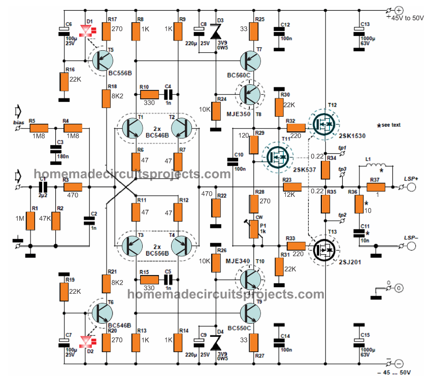
The MOSFET version of the above design can be witnessed in the below given image:
For the complete construction details, please refer to the following link:
Mini Crescendo pdf with PCB and protection circuits



Questions & Answers
Hi Sir ,
Sir I have to design an Amplifier can you help me regarding this ,
I have to design an Amplifier for a function generator , range 0hz to 15/20MHz (easier to setup)
2 amp max
120 volt max with
100-200watt
Hi Muzammil, you can use the MJE15030 transistor to amplify the signals.
Olá amigo, estou fazendo a placa de circuito impresso e logo começarei os testes
Sure Marcos, you can build the PCB and test the circuit.
Dear sir please can I add more 2N3055 output transistors for more output power ? I need strong bass even in a low volume is this possible to add thanks so much
Hi Rabiu, I don’t think that is possible, you can’t use more number of 2N3055s to increase power in this circuit.
For powerful bass you can try adding the following circuits:
https://www.homemade-circuits.com/?s=bass+sub
Hi, Swagatam,
Could you please send me the PCB. It will be of real help. Thanks
Hi Partha, you can get all the details along with the complete PCB design under this link:
https://www.scribd.com/document/502160871/37172068-e014036-155
Pls give me 6 pair 2n3055transister amplifier circuit diagram and pcb pdf and transformer voltage and amp.
What are the values for R26, R27 and R28? They seem to be added in the schematic later.
Is the schematic at the latest version?
All the schematics are correct and working.
Those resistors are 1 Ohm 1 watt
Dear sir is this suitable for public address loudspeakers? if yes which circuit should i make?
Jayanath, it is suitable, but megaphones do not require H-Fi circuitry therefore can be built with cheaper designs….the above design can be quite expensive for a crude PA audio system
Hello Swagatam. While I was considering to construct the mini crescendo original ckt design as published by Elektor Electronics in its Elektor India august 1991 issue titled as “40 watt main amplifier”, I luckily came across your this tutorial where this original ckt have been reproduced. I noticed that to improve the performance you have made some modifications to the original ckt at the input RC network, replacement of zener diodes with LEDs in the constant current circuitry and feedback components. It is evident that you have tried/ tested the original as well as the modified ckt and noticed the improvement in performance parameters. I would like to know to what extent the improvement in terms of frequency response, harmonics distortion, output power, input sensitivity(mV) for rated output(improved, if any). This will help me to decide which ckt I should go for i.e. original or modified. I also noted that the modified ckt uses the same power supply as that of the original ckt. Further, I am sure that you might be having performance parameters as mentioned in the original ckt article published in elector magazine. Still for my satisfaction I am mentioning some of these as below:
i) Output power 40 Watt into 8 ohm, 60 watt into 4 ohm for a distortion not greater than 0.01% over frequency range 20Hz – 20kHz.
ii) Max power at onset of clipping is 45 watt into 8 ohms and 65 Watt into 4 ohm load.
iii) Input sensitivity 800(850) mV for 40(45) watt and 700(750) mV for 60(65) watt into 4 ohm load.
iv) Frequency response 15Hz – 100kHz within 1 db.
Therefore, I would like to know about improvement with respect to above mentioned parameters.
Further, can we expect some further improvement by replacing the 2N3055 connected to -Ve supply rail with MJ2955 PNP transistor ofcourse along with corresponding changes in biasing network to make it fully symmetrical with the upper half ckt around driver and 2N3055 power transistors connected with +Ve supply rail.
Waiting for early response from Swagatam. Thanking you in advance.
Sarbjit Mal
Hello Sarbjit, All the circuits presented in the above article were taken from Elektor electronics magazine, none of them are mine or modified by me.
Since these are from the elektor magazine all are perfectly tested and working designs.
The last design is an upgraded version of the first designs and is rated to work from 250 watts to 300 watts.
I have little idea whether these circuits can be modified using pnp transistors or not, I recommend not to do it since the original designs are well optimized for best performance.
Hi,
I built the original Mini Crescendo by Elektor, 15 years ago and directly replaced the 2SK125 with a 2N3055, and the 2SJ50 with a MJE2955 (Metal-Transistor). Just a note: a larger heatsink is required. It’s still working flawlessly, delivering excellent sound quality with no issues.
Hi, thanks for sharing your experience with this project. I too built it some 20 years ago using 2N3055 transistors, and it worked flawlessly at one shot. I had built it on a large strip-board with a lot of care and effort, and used separate heatsinks for each of the 2N3055s….was a great experience to see the amp start working as soon as the power supply was switched ON…
Sir,
Could you please leave your suggestions for the following:
I have made 100 + 100 Watt amp using 35-0-(-)35 V Dc.
Can I drop the DC voltage from 35 V Dc to 12 V DC.
And this circuit will work in 35 Watts power in good condition.
Thanks.
Hi Nagarajan, you can do that! It will work as suggested by you!
Thanks for such a perfect tutorial….. I made with your guidance of this post…. Here is the video link for my working amplifier….
Please send me the PCB diagram. My email dpopovich@sio.midco.net
Thanks. Damir Popovich
I built this circuit (in the end) by making the PCB with DipTrace (Used LEDs instead of Zeners). Its working marvelously with Technics Speaker Boxes (as my Technics SU V303 was condemned) Swagatham Sir…. Thank you very much for publishing such a great circuit.
That’s amazing Siva, could you please send a small video clip of your work to my email? I can compensate Rs.200/- for it….
if only it is possible… not a force…keep up the good work!
Sir,
Please send your email. I have made a video and send you the same.
Siva, you can send it to
homemadecircuits
@
gmail.com
Sir,
I have sent the video to the above email.
Hi Siva, I’ll check it soon and let you know!
This could not work with the schematic with that black bg as is. Like I said. Just take a look at T14 for example, B-E junction? Can’t anyone see anything fishy there?
It’s probably a drawing mistake from me, I have corrected it now, two of them will be 680 ohms and the other one 100 ohms
the copied schematic on the black bg is wrong. don’t use as is
no pcb layout?
PCB is not strictly necessary if the assembler knows how to solder components on a veroboard. The first design is also correct, it just has a slightly different configuration compared to the last one. All these designs were tested by elektor electronic engineers.
The last design was built by me on a large veroboard and it worked at the first instant.
elektor’s crescendo was a mosfet amp, not a bjt based one.
and this amp is about 50w (on 8 ohms) not 100w, unless it’s on 4 ohms, and then not enough outputs are there and it will eventually blow if pushed a little too much.
one pair of 3055s on a complex 4 ohms load is asking for trouble.
pushing the rails above 35V is also pushing the limits as well, unless the 3055s are the most recent made, then they may stand up to some more Vce, but it would be wise to test them for secondary breakdown before using them on rails above 35V
Hi Lancy, will you please send me those PCB designs? My email is
dpopovich@sio.midco.net .Thank you.
Hello. I am trying to simulate this circuit on microcap and it seems nothing is working. Output is just some nonsense, I think I’m making a mistake that I cant figure out by myself. It really bothers me, Also tried it on Altium. If anybody could help me with that I would be really grateful.
Just write my an email if you decide to help. dowe892@gmail.com
Hello, please try the one which is shown at the end of the post…the design has been practically tested with awesome results.
fine circuit. can u send pcb diagram .thank u
thanks, If possible I’ll try to upload them soon…
thank u swag.i am very u very much interested of the nice circuit.can u explain why u have included two stage of differential pre amplifying with 547 etc .will one stage pre amplification not it be sufficient adding more stages complicates the circuit .will u give some explanatory note of significance of different pre amplifier transistor ,thus it will provide full understanding of amp circuit working.
thanks Jegadeesan, however I will not be able to explain the details in-depth because amplifiers are difficult to simulate in mind.
Basically the T5/T6 section becomes the constant current source along T1/T2 which supplies the required power to the driver stage T7—T10, while the remaining stage comprising of T11–T15 forms the power amplifier output stage….:)
Can u send the soft copy to my mail id shijuc1921@gmail.com pls
Can this circuit can be inserted with a USB slot?
if the USB slot is able to produce the required minimum level of soundsignal input then the amplifier will work with this input source
Hello Swagatam, i love to try this amp out because i have four 2N3055 just laying around doing nothing(: but sadly this transistors "BC546, BC556, BC557B, BC547B, BC556B, BC546B" are no where to be found on Indian e-commerce sites, so can you please give me an equivalent replacement for the transistors.
Thank you.
Regards.
Hi Lima, The BC546, BC556, BC557B, BC547B, BC556B, BC546B transistors are one one of the common types of transistors that one can find in any market….it's surprising that you could not find them anywhere….in my place these can be procured in bulk.
anyway you can use any 100mA or 200mA rated transistor having a 100V as the max V rating in place of these BJTs.
I don't remember the specification of these transistor.
but the circuit was +22 0 -22 volt dual supply (with 18 0 18 CT 3Amp transformer) Can I use 2N3055-MJ2955 ?
you can try it but 2N3055-MJ2955 look overrated, you can try TIP31/TIP32 instead