In this article I have explained how to calculate resistor and capacitor values in transformerless power supply circuits using simple formulas like ohms law.
Analyzing a Capactive Power Supply
Before I have explained the formula for calculating and optimizing resistor and capacitor values in a transformerless power supply, it would be important to first summarize a standard transformerless power supply design.
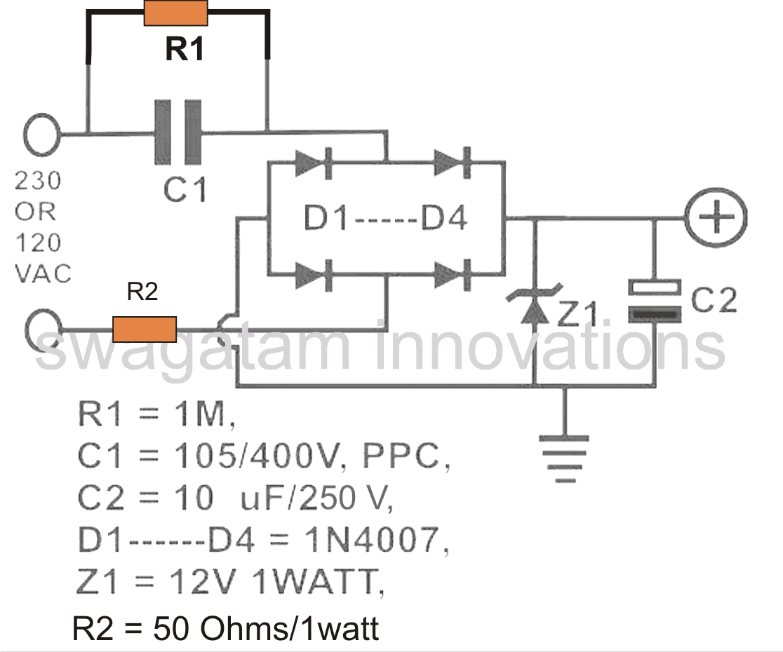
Referring to the diagram, the various components involved are assigned with the following specific functions:
C1 is the nonopolar high voltage capacitor which is introduced for dropping the lethal mains current to the desired limits as per the load specification.
This component thus becomes extremely crucial due to the assigned mains current limiting function.
D1 to D4 are configured as a bridge rectifier network for rectifying the stepped down AC from C1, in order to make the output suitable to any intended DC load.
Z1 is positioned for stabilizing the output to the required safe voltage limits.
C2 is installed to filter out any ripple in the DC and to create a perfectly clean DC for the connected load.
R2 may be optional but is recommended for tackling a switch ON surge from mains, although preferably this component must be replaced with a NTC thermistor.
Using Ohm's Law
We all know how Ohm’s law works and how to use it for finding the unknown parameter when the other two are known.
However, with a capacitive type of power supply having peculiar features and with LEDs connected to it, calculating current, voltage drop and LED resistor becomes a bit confusing.
How to Calculate and Deduce Current, Voltage Parameters in Transformerless Power Supplies.
After carefully studying the relevant patterns, I devised a simple and effective way of solving the above issues, especially when the power supply used is a transformerless one or incorporates PPC capacitors or reactance for controlling current.
Evaluating Current in Capacitive Power Supplies
Typically, a transformerless power supply will produce an output with very low current values but with voltages equal to the applied AC mains (until it’s loaded).
For example, a 1 µF, 400 V (breakdown voltage) when connected to a 220 V x 1.4 = 308V (after bridge) mains supply will produce a maximum of 70 mA of current and an initial voltage reading of 308 Volts.
However this voltage will show a very linear drop as the output gets loaded and current is drawn from the “70 mA” reservoir.
We know that if the load consumes the whole 70 mA would mean the voltage dropping to almost zero.
Now since this drop is linear, we can simply divide the initial output voltage with the max current to find the voltage drops that would occur for different magnitudes of load currents.
Therefore dividing 308 volts by 70 mA gives 4.4V. This is the rate at which the voltage will drop for every 1 mA of current added with the load.
That implies if the load consumes 20 mA of current, the drop in voltage will be 20 × 4.4 = 88 volts, so the output now will show a voltage of 308 – 62.8 = 220 volts DC(after bridge).
For example with a 1 watt LED connected directly to this circuit without a resistor would show a voltage equal to forward voltage drop of the LED (3.3V), this is because the LED is sinking almost all the current available from the capacitor.
However the voltage across the LED is not dropping to zero because the forward voltage is maximum specified voltage that can drop across it.
From the above discussion and analysis, it becomes clear that voltage in any power supply unit is immaterial if the current delivering capability of the power supply is "relatively" low.
For example if we consider an LED, it can withstand 30 to 40 mA current at voltages close to its "forward voltage drop", however at higher voltages this current can become dangerous for the LED, so it's all about keeping the maximum current equal to the maximum safe tolerable limit of the load.
Calculating Resistor Values
Resistor for the Load: When an LED is used as the load, it is recommended to choose a capacitor whose reactance value allows only the maximum tolerable current to the LED, in which case a resistor can be totally avoided.
If the capacitor value is large with higher current outputs, then probably as discussed above we can incorporate a resistor to reduce the current to tolerable limits.
Calculating Surge Limit Resistor: The resistor R2 in the above diagram forms is included as the switch-ON surge limiter resistor. It basically protects the vulnerable load from the initial surge current.
During the initial switch ON periods, the capacitor C1 acts like a complete short circuit, although just for a few milliseconds, and may allow the whole 220V across the output.
This may be enough to blow the sensitive electronic circuits or LEDs connected with the supply, which also includes the stabilizing zener diode.
Since the zener diode forms the first electronic device in line which needs to be safeguarded from the initial surge, R2 can be calculated as per the zener diode specifications, and maximum zener current, or zener dissipation.
The maximum tolerable current by the zener for our example will be 1 watt / 12 V = 0.083 amps.
Therefore R2 should be = 12 / 0.083 = 144 Ohms
However, since the surge current is only for a milliseconds, this value could be much lower than this.
Here. we are not considering the 310V input for the zener calculation, since the current is limited to 70 mA by the C1.
Since R2 can unnecessarily restrict precious current for the load during the normal operations, it must be ideally an NTC type of resistor.
An NTC will make sure that the current is restricted only during the initial switch ON period, and then the full 70 mA is allowed to pass unrestricted for the load.
Calculating the Discharge Resistor: Resistor R1 is used for discharging the stored high voltage charge inside C1, whenever the circuit is unplugged from the mains.
R1 value should be as low a possible for fast discharging of C1, yet dissipate minimum heat while being connected with the mains AC.
Since R1 can be a 1/4 watt resistor, its dissipation must be lower than 0.25 / 310 = 0.0008 amps or 0.8 mA.
Therefore R1 = 310 / 0.0008 = 387500 Ohms or 390 k approximately.
Calculating a 20 mA LED Resistor
Example: In the shown diagram, the value of the capacitor produces 70 mA of max. current which is quite high for any LED to withstand. Using the standard LED/resistor formula:
R = (supply voltage VS – LED forward voltage VF) / LED current IL,
= (220 - 3.3)/0.02 = 10.83K,
However the 10.83K value looks pretty huge, and would substantially drop the illumination on the LED....none-the-less the calculations look absolutely legitimate....so are we missing something here??
I think here the voltage "220" might not be correct because ultimately the LED would be requiring just 3.3V....so why not apply this value in the above formula and check the results? In case you have used a zener diode, then the zener value could be applied here instead.
Ok, here we go again.
R = 3.3/0.02 = 165 ohms
Now this looks much better.
In case you used, let's say a 12V zener diode before the LED, the formula could be calculated as given below:
R = (supply voltage VS – LED forward voltage VF) / LED current IL,
= (12 - 3.3)/0.02 = 435 Ohms,
Therefore the value of the resistor for controlling one red LED safely would be around 400 ohm.
Finding Capacitor Current
In the entire transformerless design discussed above, C1 is the one crucial component which must be dimensioned correctly so that the current output from it is optimized optimally as per the load specification.
Selecting a high value capacitor for a relatively smaller load may increase the risk of excessive surge current entering the load and damaging it sooner.
A properly calculated capacitor on the contrary ensures a controlled surge inrush and nominal dissipation maintaining adequate safety for the connected load.
Using Ohm's Law
The magnitude of current that may be optimally permissible through a transformerless power supply for a particular load may be calculated by using Ohm's law:
I = V/R
where I = current, V = Voltage, R = Resistance
However as we can see, in the above formula R is an odd parameter since we are dealing with a capacitor as the current limiting member.
In order to crack this we need to derive a method which will translate the capacitor's current limiting value in terms of Ohms or resistance unit, so that the Ohm's law formula could be solved.
Calculating Capacitor Reactance
To do this we first find out the reactance of the capacitor which may be considered as the resistance equivalent of a resistor.
The formula for reactance is:
Xc = 1/2(pi) fC
where Xc = reactance,
pi = 22/7
f = frequency
C = capacitor value in Farads
The result obtained from the above formula is in Ohms which can be directly substituted in our previously mentioned Ohm's law.
Let's solve an example for understanding the implementation of the above formulas:
Let's see how much current a 1uF capacitor can deliver to a particular load:
We have the following data in our hand:
pi = 22/7 = 3.14
f = 50 Hz (mains AC frequency)
and C= 1uF or 0.000001F
Solving the reactance equation using the above data gives:
Xc = 1 / (2 x 3.14 x 50 x 0.000001)
= 3184 ohms approximately
Substituting this equivalent resistance value in our Ohm's law formula, we get:
R = V/I
or I = V/R
Assuming V = 220V (since the capacitor is intended to work with the mains voltage.)
We get:
I = 220/3184
= 0.069 amps or 69 mA approximately
Similarly other capacitors can be calculated for knowing their maximum current delivering capacity or rating.
The above discussion comprehensively explains how a capacitor current may be calculated in any relevant circuit, particularly in transformerless capacitive power supplies.
WARNING: THE ABOVE DESIGN IS NOT ISOLATED FROM MAINS INPUT, THEREFORE THE WHOLE UNIT COULD BE FLOATING WITH LETHAL INPUT MAINS, BE EXTREMELY CAREFUL WHILE HANDLING IN SWITCHED ON POSITION.



Questions & Answers
No you cannot do that, unless the output load operating voltage doesn't match the input mains level, adding caps won't work, rather would become dangerous for the LEDs.
hi guys ,, i have done this circuit as you illustrated in the diagram…. but my output is just 1.5v after brige circuit… can u help me with this
Remove the zener and the capacitor and then check
Hello, thanks for the good article. Really usefull. Im an engineer from Venezuela.
I have a doubt. If i want to test different loads, and i short circuit the output (for maximum current scenario) what is expected to happend. I was told that the voltage Will drop. But i don see why.
Thanks in advance.
Glad you liked it, if you short circuit a capacitive power supply output, the voltage will drop to zero without any harm to any devices. It is because the capacitor will restrict current beyond the rated limit causing the voltage to drop.
Sir,
Please explain what type calculation behind "220v X 1.4=308v",why we using and where we get 1.4 here to multiple, any standard or calculation.
Thanking you,
kumaran muthu
Kumaran,
Please research "RMS voltage" you will get answer
Hi sir!I'm a student.My project is transformerless power supply (220VAC-12VDC). I want to know about how to caculate C1 and R1 by using real formular. Can you help me?
Hi sokleang, you can refer to this article for the details:
https://www.homemade-circuits.com/2015/01/calculating-capacitor-current-in.html
R1 is not important, you can use any resistor above 330K and below 2M2 for this resistor
Hi sir.how to known value of C1 R1?
Hi Sir,
how I will calculate the current limiting resistor of transformerless power supply. Please feedback my question
Hi Joni, It will need to be calculated as per the specifications of the load that you intend to connect at the output
you can use Ohm's law for calculating the parameters
Hi there.. I need to get 5VDc 1A output from 220VAc 60hz.. Please give me the C and R value
1 amp is too high and is not recommended from capacitive circuits.
hello dear swagatam , can i use above ckt as power supply for PIR motion sensor ckt
Hi Shankar, I won't recommend it, better to go for a SMPS adapter, your cellphone adapter will do the job nicely
Hai sir, just tell me am i thinking right, i want to use lm2596 to produce 36volt and 3 amps, im planning to give transformerless ac to dc converter as a input of lm2596, i confusing that what is the voltage and current for the input and how do i get from dropping capacitor
Hi, 3 amp is too high for a capacitive power supply…I would advise you to build an SMPS instead
Dear sir , Any possibility to design 12 v /30 amp current with x rated capacitors . will it work ? Badly needed for radiology use . ADV thanks for your reply.
Hi Ananad, a 1uF/400V capacitor will give you approximately 50mA current out, so now you can estimate the required value for getting 30 amps
Hi,
I have done this project using 2.2uF, 100R and 5.1V Zener. i got output voltage perfectly but i got 90V DC after bridge, How can i reduce that voltage??
Hi, you can reduce it either by adding a zener diode across the bridge or an SCR or a power BJT. The SCR version is shown below:
https://www.homemade-circuits.com/scr-shunt-for-protecting-capacitive-led/
Hi Swagatam
my question is , is there any difference between placing zener diode before or after the electrolytic capacitor?
thanks
Hi Abba, there’s no difference, both will have the same effect on the output
Hi dear Swagatham,
I have a doubt related to this particular question of Mr.Abba.
I have seen in some Capacitor based transformerless power supplies, the zener diode is connected before the bridge rectifier. If I make more clear my question, consider the above circuit by you, assume ZD1 connecting after C1, R1 junction and the R2. (As per my knowledge, before bridge rectifier, the supply is AC voltage.) If we connect ZD1 before bridge will stabilize the output voltage….?
Thanks in advance.
Dear Anil,
Connecting the zener before the bridge will allow only half cycles of the AC to pass across the output, and will ground the other half cycles, so the output current will become 50% less.
Therefore connecting the zener before the bridge will waste or reduce 50% power.
very nice…good work but sir I need 15v power supply 10A using ferrite core
thank you sunshne, I do not have the design at the moment, but you can try designing it yourself using the following tutorial
https://www.homemade-circuits.com/how-to-design-a-flyback-converter-comprehensive-tutorial/
okay thanks let me try
good day Sir,,, please i need your help. someone asked me to build automatic power restoration alarm.. please help the circuit diagram thanks
Sunshine, please provide more info regarding the alarm specification.
Hi Swagatam, How are you ?
I am electronic hobbyist user. I build circuit as given. It is working but R2 (56 ohm 2W) , bridge rectifier and filter capacitor 10uf 250v all component get hot. only change I done is that change value of R2 from 50 ohm to 56 ohm (because I did not get 50 ohm).
Hi Prashant, That looks strange. I can understand R2 getting warm or slightly hot, but the diodes shouldn’t become hot at all because they are 1 amp rated and the 105 cap can produce only 50mA. Similarly with the presence of the 12V zener, the 10uF/250V shouldn’t become hot either, I think there’s some other problem with your circuit, which you must diagnose. Let me know if you have anymore doubts.
hi, many thanks for your great explanation of transformer-less power supply
just a question, I will glad if you could help me
I have a motor start capacitor, aluminum body, 450v, 20uF capacitor, something similar to this image
https://encrypted-tbn0.gstatic.com/images?q=tbn:ANd9GcSe0yrPEhBHj-U5kUy7Kjqe9Y7mOSs6wj-yoYpET7U-sgK57iY2ZA
can I use it to make a power supply? according to the formulas, it can provide 1.6 amps at 308v dc, as your explanations, which is very convenient, and if that is possible, can I use something like lm317 to make a variable power supply from it?
again thanks
Hi, thanks very much! Glad you are liked it! Yes, no doubt you can use the shown 20uF/400V capacitor, but the problem with this type of power supplies is the surge current. when you switch ON power the capacitor will act like a short circuit for a few milliseconds which will be enough to the fry the LM317 instantly.
However a mosfet based regulator might do the job, and you can use it as a variable capacitive power supply. Here’s a diagram that you can try:
hi
again thanks for your answer
I just read the pages related to mosfet based regulator transformer-less power supply, and your example provides 350 mA at 310 V dc with a 5 uF capacitor, so with mine 20 uF capacitor I would get 1.4 Amps, right?
if I use this circuit as a variable voltage power supply, I can bring than the voltage for example to 30 V or 12 V via the variable resistor R3 in the attached picture, and of course rest of power ((310-30)*current) must be dissipated through the mosfet heat sink, right again? now my question is that how much current I can get from this circuit at 30 V? can it light a 30 V 30W power led?
Practically a 1uF will give you 50mA output, so 20uF will produce 1 amp.
using mosfet will allow down to 9V, using BJT 2V.
remaining power will be dissipated through heat.
30V 30w is definitely achievable.
Hi Swagatam,
Firstly let me appreciate your activity.
On the other hand I would ask your opinion regarding a “flame detector circuit” using ionization principle.
It consists in two wire rods placed in a flame ( e.g. burner) connected to the circuit so it detects instantly the fire presence.
Did you have such a project knowledges?
Waiting for your kindly answer,
Sorin
Hi Sorin,
Sorry, I haven’t investigated this theory yet, so it’s not known to me. A more effective method of detecting fire is by detecting smoke or gas.
I need a 120v 20mA ckt. What will be the electrolytic capacitor to reduce the ripple after bridge ?
for 120V you will need a 120V zener assuming the input is 220V.
the electrolytic can be 1000uF/25V
Dear Swagatham
If I use 224pf/400V capacitor (220VAC, line frequency 50Hz) the output current would be 15.7ma. There is no need for any zener diode (for voltage regulation) and series resistor (for current limiting) for driving a single 20ma RED LED (vF1.8V). Is it correct….?
Maximum howmany 20mA RED LEDs can be connected in series using the above 224pf capacitor ….?
Dear Anil, yes technically that’s correct, but the occasional switch ON surge could soon destroy the LED, therefore a resistor and zener diode is necessary to prevent this.
After rectification through 4 diodes and a filter capacitor, the deisgn will support a minimum of 300 / 3 = 100 nos of RED LED in series.
For this configuration, only a limiting resistor should be enough, although a 300V zener across the supply line may guarantee a better safety to the series.
Hello, what values of resistors and capacitors should I use to put in action a break coil (105 vdc, 0.38 Amps) from a main source 220 vac? Thank you in advance!
You can use a 8uF/400V capacitor. Make sure to rectify the output through a bridge diode and capacitor, and also use a 110V zener diode across the output
Hi Swagatam. I am repairing a 240v saw. I need to replace the voltage dropper capacitor in the circuit feeding the gate of the triac. Its a smd 0805 ceramic. Any idea of the value. Thanks in advance.
Mark.
Hi Mark, according to the online information this can be a 0.1uF/16V SMD capacitor
Hi Swagatam, thank you for your time, very much appreciated.
Mark
Hi I m following u for a long time. I show many a circuits for making a transformerless power supply given by you.i tried a few of ten but theres always a problem of heating or over voltage or undervoltage..I tried every thing ever a 2watt 50 ohms resistor starts heating up. Plz suggest me a circuit using 105/400 capacitor and plz show me how to connect maximum no of leds ( white straw head led 5mm)
Hi, please replace the 50 ohm resistor with a 10 resistor, it will not heat, or you an also replace it with an NTC thermistor for better surge control.
You can connect 90 numbers of 3.3 V LEDs rated at 20 mA in series. Remember to put a 300 V 1 watt zener diode across the +/- of the LED string or after the bridge rectifier