This circuit will allow you to control any electrical gadget from any part of the world through your cellphone remotely, that too without spending a penny for the individual commands.
Circuit Concept
Whether it’s you vehicle, your basement door, your mansion gate or simply the air conditioner of your house, everything can now be switched by just a flick of your cell phone button.
And yes, it’s completely fool proof, meaning no false triggering is possible through any other cell phone signals, it works only through the owners cell phone commands.
The explained circuit must be employed strictly for operating only the following specified equipment:
All domestic electrical appliances like, lights, fans, motors, TV sets, refrigerators, Air conditioners, washing machine, porch lights, garage door, house gate, basement gate or entrance, car ignition, car doors, water heater etc.
The concept has been already discussed in one of my previous articles – How to make a GSM car security system, and the going about is unbelievably simple.
However, the above article deals with a system that involves DC control features and therefore is not suited for controlling AC appliances.
The unit discussed here is a universal device and can be used for operating all types of electrical gadgets from any part of the globe, just by making a single blank call to the systems number.
The system will faithfully respond to every call made from your cell phone and will alternately switch the connected load ON and OFF as per your instructions.
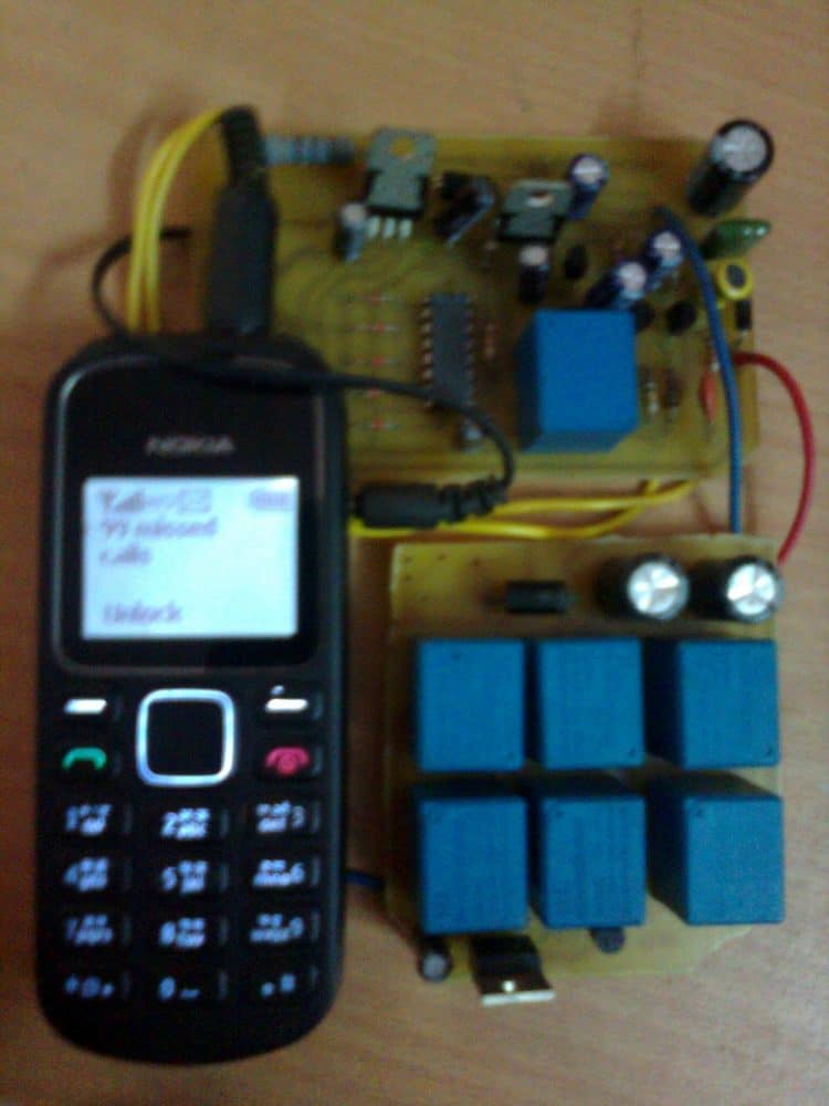
The concept is impeccable, as it has been tested by me thoroughly since last three years with flying results.
Basically the unit employs a very fundamental principle of converting the ringtone of a cell phone into a command output for operating a relay.
This cell phone acts as a modem and is permanently attached with the internal control circuit of the unit. The modem cell phone is initially made ready by putting a SIM card inside it and by configuring the essential assigned numbers into its phone directory.
These assigned numbers are the only numbers to which this modem responds. Therefore you would want to assign only those numbers through which you may like to make a call to the “system”.
For safety reasons more than one number is assigned to the modem so that in case one of your cell phones is out of order or has low battery, you always have the option of using the other cell phone for triggering the system.
The biggest advantage of the GSM cellphone remote control circuit is that, any cheap NOKIA cell phone can be used here as the modem and therefore there’s no fear of the modem becoming obsolete.A simple yet effective cell phone remote control switch details has been discussed here with complete schematics and step by step tutorial.
UPDATE:
Looking for an advanced solution? Read more below:
Advanced Microprocessor Based GSM Remote Controller
If you have sufficient prior knowledge of electronics, you should be making this complete unit within a days time. Let's begin the discussion. Basic Concept The idea here is to use an ordinary NOKIA 1280 cell phone as the modem attached permanently with a switching circuit. This entire unit now becomes the receiver unit.
The modem cell phone NOKIA1280 is assigned with desired numbers, for example the owners cell number and a few other numbers of the owners family members.
When the modem cell phone is called through these assigned numbers, the modem ring tone becomes active and this ring tone is applied to the control circuit and is processed for operating a relay and the connected load.
Since the modem cell phone needs to be attached permanently inside the switching unit, it needs to be charged at regular intervals so that it remains functional all the time.
For this, a separate cell phone charger module has also been incorporated along with the main circuit which keeps the modem cell phone battery always up to date and fully charged.
It is quite obvious that the attached cell phone modem will need a SIM card, which will need to be maintained as we do for normals cell phone operations.
I have explained the building process. You will have first get or procure the following materials or parts for making this unit. I would suggest not to make the Printed board initially, it would better to first test the working over a general board and if thing goes then you would want to transfer it over a well designed P-C-B.
Bill of Materials
All resistors are 1/4w 5% CFR unless otherwise stated.
- R1 = 22k
- R2 = 220 OHMS
- R3,R11,R12 = 100K R13 = 100 Ohms
- R4,R6,R7,R9 = 4.7K
- R5 = 1K,
- R8, R10 = 2.2M
- C1,C4,C5 = 0.22uF DISC TYPE
- C2,C3 = 100uF/25V
- T1,T2,T4,T5 = BC 547B
- T3 = BC557 B
- ALL DIODES = 1N4148 IC1 = 4093
- RL1, RL2 = RELAY 12V/300 OHMS SPDT
- JACK = 3.5mm AUDIO JACK
- CELL PHONE MODEM = NOKIA 1280
Circuit Diagram
Understanding the Schematic Diagram
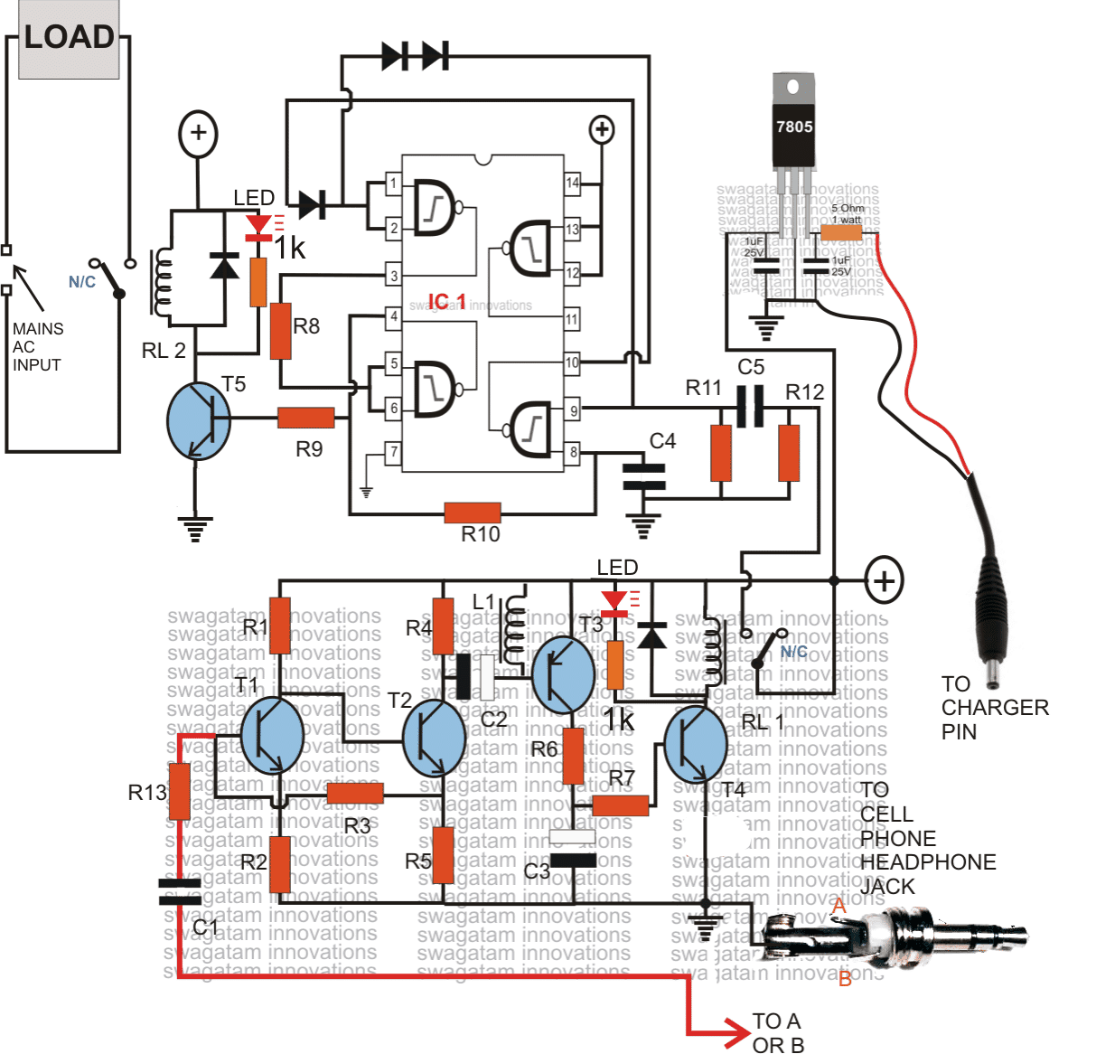
The above schematic of the proposed cellphone controlled remote circuit is rather very easy to understand. It may be divided into two main stages, the lower stage consisting of the transistors is a simple audio amplifier, the upper stage consisting of IC is the flip flop triggering stage.
When a signal is present at the 3.5mm jack, which might be the input ring-tone from the cell phone modem., T1, T2 amplifier to some greater level, which is further amplifier by T3, T4 to a level is becomes sufficient for triggering the relay RL1. RL1 instantly connects the supply to the input of the flip flop at C5, via its N/O contacts.
Note that RL1 will remain switched ON as long as the ring tone is present and will switch OFF the moment the ring tone or the signal over the 3.5mm jack is canceled. C3 makes sure that the relay does not get rattled by any insignificant signals or RFs.
L1 has been installed also for the same reason, that is for eliminating unwanted signals and making sure that T3, T4responds only to valid ring-tones.
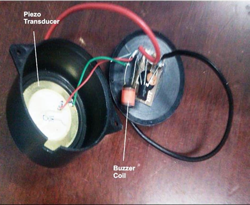
L1 is a buzzer coil, as used in piezo electric buzzers, or may be hand made by winding 1000 turns of 36SWG super enameled wire over a small ferrite core, size and shape does not matter. Image of L1, inside a buzzer
The period for which RL1 remains switched ON will have no consequence on the flip flop operation, the flip flop will switch ON and OFF in response to every subsequent missed call made from the owners cell phone.
The section comprising the IC 7805 is battery charger section, which needs to be connected to the battery charger input of the cell phone.
The charger will keep the cell phone battery always charged so that it remains functional all the time. The above circuit has been thoroughly tested and confirmed by me, so if you make everything as shown in the above diagram, it should start working immediately.
How to Assign Numbers Inside the MODEM CELL PHONE It's very easy. Just follow the following steps. Save the names and the numbers which are important and through which you want the above unit to be operated.
Next select a particular name-->--press scroll right-->--"contact details" will be displayed-->-- press options-->--scroll down-->-- select "assign tone"-->--select a ring tone which has a sustained, non-breaking tune-->-- do OK. Repeat this for all the desired numbers. Now go to settings, go to tone settings and select "empty", press OK.
That means now you have switched OFF the default ringtone and no ringtone will be audible for any numbers other than the above assigned ones.
So you can be rest assured that the system will not respond to wrong numbers or any unknown numbers. It will respond to only the calls made from the assigned numbers.
How to Power the Unit
The circuit needs to be powered through a DC12V/500mA or 1 Amp SMPS adapter.
The load may be any electrical appliance like lights, fans, AC, fridge or anything that you may like to switch using this system.
Video Clip showing the circuit functioning of the prototype
WARNING AND DISCLAIMER – THE PROPOSED DEVICE MUST BE USED FOR OPERATING ONLY THE COMMON HOUSEHOLD ELECTRICAL SYSTEMS AND PARAMETERS. THE PROPOSED CELL PHONE OPERATED SWITCH MUST NEVER BE USED FOR ANY OTHER INTENTIONS OR PURPOSE WHATSOEVER, AND THE AUTHOR TAKES NO RESPONSIBILITY FOR ANY LOSSES THAT MIGHT OCCUR IN CASE THE UNIT IS USED FOR OPERATING ANYTHING ELSE OTHER THAN WHAT'S BEEN SPECIFIED IN THE ABOVE ARTICLE.



Questions & Answers
yup.. not based on DTMF
The resistor must be in series with the LED that's only important, it doesn't mater on which side it's connected.
Hi….
This Circuit Work On 10 Hp Delta Star Starter?????
And Mobile Charger Automatic Cutoff Mode Or Not???
Full Time Charging Battery Is Damaged….
i want to buy this circuit
the relay contact rating determines the load handling capacity of the circuit, so it can be rated accordingly and used for handling any desired load or wattage.
Dear Pete,
Recently I got the oppurtunity to confirm its value, it's around 40mH….
hi! sir can u advice me, sir i have a project in my school that can control all appliances in the house using call and text can u give me any advice or a schematic plz i need help sir!
sir can u help me i am building a project that control appliances, using call and text can u give me advice what will i do or can u give me schematic sir, that would be a big help sir! plz help!
Hi Clied,
For text message control you will have to employ a GSM module, I don't have much idea about them, so you might have to take the help from some other source.
hello sir, i have a question. what is the voltan for the supply ?
Disconnect RL1 link with the upper circuit and check the lower stage separately first.
RL1 will only operate momentarily on power switch ON, the LED connected parallel to RL1 coil will illuminate only for a second and then switch OFF, this might happen or might not happen….but under any case RL1 will not switch ON permanently when powered initially.
RL1 will switch ON only in response to a ringtone and will hold only until the ringtone is not cutoff, once the ringtone from the phone is disconnected, RL1 will instantly deactivate.
First confirm this then you can proceed with the upper circuit.
…presently I am not selling any kits so would be unable to provide them to you!
Regards.
I have shown the example image of L1 inside the buzzer, it's exactly what would suit, alternatively any 40mH coil would work
from dr vivek,
I needed a circuit to operate street lights of my farmhouse (60wTT X 3 bulbs) when I reach the gate guiding me to the door. If I purchase the circuir from you could you suggest me additional modifications. However I have to depend on an electronics technician based on your diagram plz help me.
Dr Vivek, what modifications do you want to make in the system?? Please specify them.
Regrettably dear friend but this project is not only unsafe but also dangerous if not used by normal people brains.
Imagine if a person called us your number by mistake, he will have access to pasijen that you have built to be used only for yourself.
This is a project for beginners in electronics.
To have self control you control what you bu
sir i am vijay and i want ask you
that, sir please give me pcb layout because i am not under standing its power supply
Sir can't we replace the 4093 by 4011?
and my second question is; is it possible to see the output (result) by using only "the upper circuit"
hello sir, am trying to simulate the above circuit to operate a dc 12v motor using national instruments and i have encountered some problems, firstly the l1 buzzer is not available, what other specifications would i use?secondly can i use a switch in place of the relays? third what is a suitable replacement of the 7805 ic for the charging circuit?
hello edd, use a 40mH coil for L1,
relays are transistor/voltage driven components how can switches be replaced with them?
7805 can be replaced by any standard/suitable 5V regulator circuit or IC
hi ,
excellent article and concept..
i have a pumpset arounf 1/2 a kilometer away from my house,which pumps in water from the river.can the pump motor be toggled using this circuit,it is an 5 hp motor.if not can u suggest a method for doing so..i mean the changes to be incorporated for this functionality
hi, thanks, yes you can use the above circuit for this application, just upgrade RL2 for handling higher current, you can replace it with a 30amp relay.
how the +ve sign is a dc supply connected from only one side
how the +ve sign is a dc supply connected from only one side
I did not understand your question…
I mean why the dc supply has only one branch ( +ve only )
and not 2 branches +ve and -ve )
The lines with the earth symbols must be all connected with the negative of the power supply.
another question mr Swagatam did you mean that i'll connect the circuit with ac voltage source
i mean is the main Ac input is a connection between the circuit and the ac current from the wall
(+) will go to +12V and the earth symbol to the -12V of a 12V DC adapter output terminals…..AC mains may be used for operating the load across RL2 contacts..
you mean that there are 3 dc adapters or 1 only gives the 3 rails
all (+) to be made common and joined with the (+) of the power supply, same for the "earth" rails.
Sir my circuit is not working….i have made ur previous project in which the circuit is on for only a short period till the phone rings i.e half part of dis circuit…. Without relay it is working properly bt when i connect relay it can not switch the relay….
I cant understand y it is happening so….
Plz help me…
My email id is rohitraj0000@gmail.com
Deepak, you should make and test the upper flip flop circuit separately for confirming its operations. Once it's confirmed you may proceed to integrate it with the lower section. You may refer the second circuit from the following link for a detailed info regarding the flip flop circuit design:
https://www.homemade-circuits.com/2011/12/build-these-simple-flip-flop-circuits.html
The same problem is faced by me… Only for lower circuit it can not enrgies the relay…
Sir
Can we use a camera mobile phone with 3g support to receive a video call from the user after a alert call been made ?
I don't think it would be possible using a simple technology as above.
Dear Swagatam,
Can You Send this pre packed gadget, i will pay for it
Dear Ajay, presently I am not manufacturing this unit so I am sorry I wouldn't be able to send it to you.
sir you give me the spec of IC4903
sir, how can i connect relay 1 and relay 2 ….need more
hai sir plz send me this project full schematic
muralisanu97@gmail.com
hello sir .i like your project.. its a wonderfull. i need your big gift.
please send me this project FULL SCHEMATIC
MY G-MAIL–muralisanu97@gmail.com
Thanks for sharing the brilliant idea and circuit,sir.
*Are these 3.5 mm headphone pins available at the stores?
I feel it difficult to peel off the outer sheath of my headphone jack to take the pin out.
*What is the inductance of the buzzer coil used?Could it be replaced by one of the coils of a miniature driver transformer?
*Why T3 is a pnp transistor..?
I'am a beginner..
Regards
-Pranav
Thank you Pranav,
Yes 3.5mm jacks are available as spare with an unscrewable plastic cover.
But this circuit is not for a beginner, you will have to first learn all the basics of electronics, do plenty of practicals with simple circuits and then attempt the the above project.
i make this circut …but it is not working …..what can i do? plz help me
tell me which parts are not shown to the diagramme
the circuit is perfect in every way, what is happening with your circuit? is RL1 activating when the modem is called??
When i m connect the supply the relay one is automatically open i cant find problem plz help me
did you call the modem phone….RL1 will stay activated only as long as the call is connected.