• Skip to main content
  • Skip to primary sidebar

Homemade Circuit Projects

Need circuit help? Post them in the comments! I've answered over 50,000!

Blog | Categories | About | Contact | Calculators-online
You are here: Home / Electronics Theory / How Flex Resistors Work and how to Interface it with Arduino for Practical Implementation


How Flex Resistors Work and how to Interface it with Arduino for Practical Implementation

Last Updated on January 4, 2024 by Swagatam 3 Comments

As electronics enthusiasts we may come across many kinds of resistors, from small fixed resistor to high current bulk rheostat. There are humongous classifications among resistors, but here we will focus on a particular kind of resistor called “flex resistor” and learn how it works.

Table of Contents
  • Specifications overview:
  • How Flex Resistors work?
  • Basic schematics on how to use:
  • Arduino Interface
  • Conclusion:

As the name signifies a flex resistor is flexible and also changes its resistance when it gets bend. This sensor device is boon for those who may be working in the field of robotics, medical devices, angular displacement measurement, motion sensing game development, etc.

There are limitless numbers of applications if you peak your imagination to maximum.

warning message: electricity is dangerous, proceed with caution
Flex Resistor

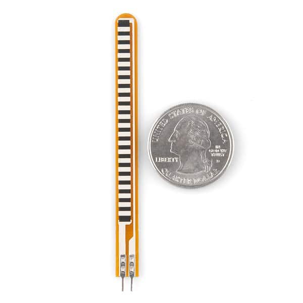
Flex resistor compared with a coin.

Specifications overview:

The flex resistor measures 2.2 inch on length (may vary), having a resistance around 10K ohm when it is flat and has a huge tolerance range of +/- 30%. This means if you bought two similar flex resistances, its resistance to angular bend ratio may vary a bit. This parameter must be considered when you calibrate your design.

It has working temperature range of -35 degree to +80 degree Celsius. It has power rating of 0.5 watt continuous and 1 watt peak. The predicted life cycle is greater than 1 million times.

There is bend limit for every flex resistor please check the data sheet for the respective flex resistors; if you exceed those limits you may damage your flex resistor.

There are two classifications of flex resistor:

1) Unidirectional

2) Bidirectional

Unidirectional: This type of flex resistor can be bent only in one direction within their bend limit. If we do the same on the other direction, we may damage it.

Bidirectional: This resistor can be bent on either direction within their bend limit.

So, choose the right flex resistor depending on your application.

How Flex Resistors work?

There is a conductive ink sandwiched between two plastic films. Electrodes are placed either sides of conductive ink. The conductive ink consists of microscopic particles which are electrically conductive.

When the resistor is flexed the microscopic particles move away from each other, and the resistance increases. Vice versa is also true.

Basic schematics on how to use:

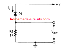
Here is a basic schematic of a flex resistor application.


basic schematic of a flex resistor application

The flex resistor has limitless applications if you know how to use them. Here is a simple op-amp circuit paired with a flex resistor. You can set threshold to trigger the output, if you use an op-amp in comparator mode. The suggested op-amps are LM324 and LM358; you may also give a try for 741.

You can also pair it with arduino, by giving the flex resistor to analogue read pin of arduino with pull down resistor. No additional libraries are required.

Arduino Interface


how to interface flex resistor with Arduino

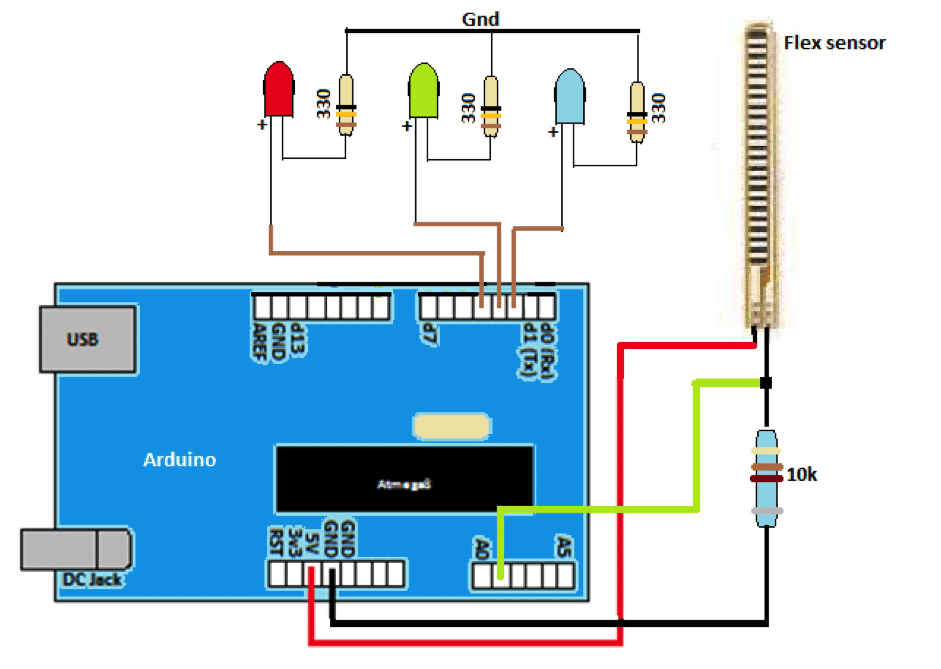
Here is an illustration of simple angle sensing for flex resistor. If the flex resistor is flat, blue LED illuminates, if the resistor is flexed to an angle x (say) green LED illuminates, if it flexes greater than x then, red LED illuminates.

Flex resistors can be also seen in applications which demand simulation of complex movements and patterns, for example it's used for studying precise human finger movements, where the motion of the finger is tracked by flex resistor, decoded and displayed on a screen. This principle may be adapted by game developers to develop motion based game.

Conclusion:

Through this simple electronic component, we find huge spectrum of applications. There is no limitation to deploy the component on our daily used electronics, the only limitation may be in our imagination to deploy those in the right way.

You'll also like:

  • 1.  How an Accelerometer Works
  • 2.  Diode Rectification: Half-Wave, Full-Wave, PIV
  • 3.  How Electret Microphones Work – Full Tutorial and Diagram
  • 4.  How to Connect Resistors in Series and Parallel
  • 5.  Capacitive Voltage Divider
  • 6.  How to Make a Zero Crossing Detector Circuit

Filed Under: Electronics Theory Tagged With: Arduino, Flex, Interface, Practical, Resistors, Work

About Swagatam

I am an electronics engineer and doing practical hands-on work from more than 15 years now. Building real circuits, testing them and also making PCB layouts by myself. I really love doing all these things like inventing something new, designing electronics and also helping other people like hobby guys who want to make their own cool circuits at home.

And that is the main reason why I started this website homemade-circuits.com, to share different types of circuit ideas..

If you are having any kind of doubt or question related to circuits then just write down your question in the comment box below, I am like always checking, so I guarantee I will reply you for sure!

Previous Post: « Understanding Capacitor Codes and Markings
Next Post: Understanding Color Codes of Resistors with Practical Examples »

Reader Interactions

Comments

  1. abdulsttar says

    April 3, 2024 at 4:27 pm

    categized the angler measurement devices with the use of flexible resistors

    Reply
  2. Sonja Sinor says

    December 10, 2019 at 11:44 am

    I will immediately grab your rss as I can not find your e-mail subscription link or e-newsletter service. Do you have any? Kindly let me know so that I could subscribe. Thanks.

    Reply
    • Swagatam says

      December 10, 2019 at 12:24 pm

      Thank you, you can find the subscription link just under the article posts.

      Reply

Need Help? Please Leave a Comment! We value your input—Kindly keep it relevant to the above topic! Cancel reply

Your email address will not be published. Required fields are marked *

Primary Sidebar

circuit simulator image

Subscribe to New Posts


Categories

  • Arduino Projects (89)
  • Audio and Amplifier Projects (132)
  • Automation Projects (17)
  • Automobile Electronics (101)
  • Battery Charger Circuits (83)
  • Datasheets and Components (104)
  • Electronics Theory (143)
  • Free Energy (37)
  • Games and Sports Projects (11)
  • Grid and 3-Phase (19)
  • Health related Projects (25)
  • Home Electrical Circuits (12)
  • Indicator Circuits (14)
  • Inverter Circuits (88)
  • Lamps and Lights (142)
  • Meters and Testers (69)
  • Mini Projects (46)
  • Motor Controller (64)
  • Oscillator Circuits (27)
  • Pets and Pests (15)
  • Power Supply Circuits (108)
  • Remote Control Circuits (50)
  • Security and Alarm (64)
  • Sensors and Detectors (101)
  • Solar Controller Circuits (59)
  • Temperature Controllers (42)
  • Timer and Delay Relay (49)
  • Transmitter Circuits (29)
  • Voltage Control and Protection (39)
  • Water Controller (36)


Other Links

  • Privacy Policy
  • Cookie Policy
  • Disclaimer
  • Copyright
  • Videos
  • Sitemap


People also Search

555 Circuits | 741 Circuits | LM324 Circuits | LM338 Circuits | 4017 Circuits | Ultrasonic Projects | SMPS Projects | Christmas Projects | MOSFETs | Radio Circuits | Laser Circuits | PIR Projects |

Social Profiles

  • Twitter
  • YouTube
  • Instagram
  • Pinterest
  • My Facebook-Page
  • Quora
  • Stack Exchange
  • Linkedin


  • Recent Comments

    • Farmtech on Free Energy Generator Circuit – The N-Machine
    • Nitesh Agrawal on How to Design Simple LED Driver Circuits
    • Swagatam on How to Design Simple LED Driver Circuits
    • Nitesh Agrawal on How to Design Simple LED Driver Circuits
    • Swagatam on Prevent Relay Arcing using RC Snubber Circuits

    © 2025 · Swagatam Innovations