In this article I have explained regarding how to design and make your own customized high current wireless battery charger circuit using wireless power transfer concept.
Introduction
In many of my earlier articles I have comprehensively discussed wireless power transfer, in this article we will go a step ahead and try to learn how to design a high current version of the same which can be applied for any high power wireless transfer operation such as for charging an electric car battery etc.The idea of optimizing a wireless power transfer circuit is quite similar to optimizing an induction heater circuit, wherein both the concepts can be seen utilizing the optimization of their LC tank stage for achieving the desired power output at the highest possible efficiency.
The design can be implemented by utilizing the following basic circuit stages in it:
The Transmitter Circuit will include:
1) An adjustable frequency oscillator.
2) A half bridge or a full bridge circuit (preferably)
3) BJT/Mosfet driver stage.
4) an LC circuit stage
The Receiver circuit stage will include:
1) Only the LC circuit stage.
An example circuit for the proposed high current wireless battery charger can be witnessed in the following diagram, for simplicity sake I have eliminated the use of a full bridge or half bridge circuit, rather have incorporated an ordinary IC 555 circuit.
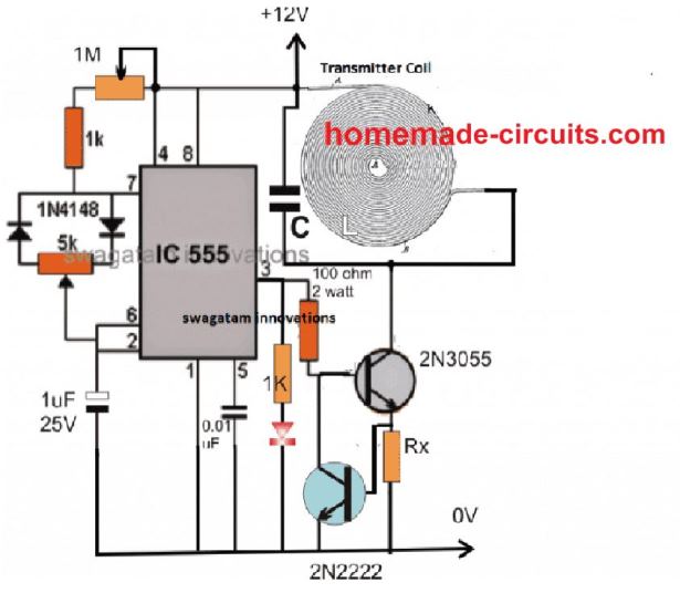
The above design represents the transmitter circuit of the high power wireless battery charger circuit using a IC 555 PWM circuit.
Here the output could be a little inefficient since the conduction process is single sided and not a push pull type.
Still, if this circuit is correctly optimized a decent high current power transfer can be expected from it.
Please remember that the wire inside coil must not be a thick single core wire, rather a bunch of many thin wires. This will allow better absorption of current and therefore higher rate of transfer.
How it Works
The IC 555 is basically configured in its standard PWM mode which can be adjusted using the shown 5K pot, there's another adjustable resistor in the form of 1M pot which can used for optimizing the frequency and the resonance degree of the circuit.
The PWM pot could be used for adjusting the current level while the 1M for peaking the resonance level of the LC tank circuit.
The LC tank circuit can be seen attached with the transistor 2N3055 which powers this LC stage with a frequency corresponding to its base frequency from pin#3 of the IC.
How to Select the LC Components.
Selecting the LC parts optimally can be achieved by following the instructions as furnished in this article which explains how to optimize resonance frequency of an LC tank network.
Basically if you know the frequency value, and either L or C, then the unknown parameter can be easily calculated using the suggested formula or this LC resonance calculator software.
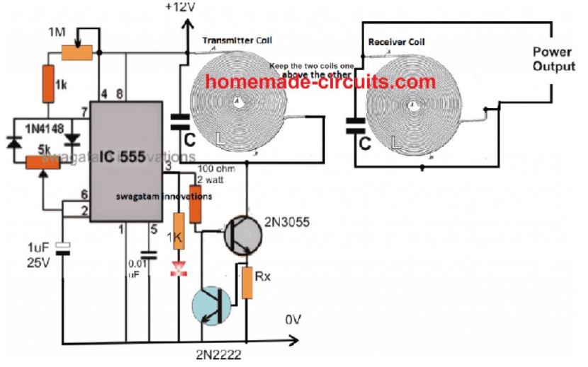
The Receiver Circuit
The coil for the receiver circuit for this high current wireless battery charger is exactly similar to the transmitter coil. Meaning, you can simply use a single continuously running coil from start to end, and add a resonating capacitor across these terminals.
Make sure the LC values are exactly similar to the Tx LC values. The set up can be seen in the following image:
The 2N2222 transistor is introduced to make sure that while adjusting the resonance, the 2N3055 is never subjected to an over current situation. In case this tends to happen the over current develops an equivalent amount of triggering across Rx sufficient to activate the 2N2222, which in turn shorts the 2N3055 base to ground inhibiting it from conducting any further and thus preventing the device from a possible damage.
Rx may be calculated using the following formula:
Rx = 0.6/Max current Limit of the transistor (or the wireless power transfer)
Adding a voltage regulator for charging the battery:
In the above diagram, the output from the receiver should be attached with a voltage regulator circuit such as using an LM338 circuit or an opamp controller circuit for making sure that the output can be safely fed to the intended battery for charging it.
If you have any further queries, please feel free to express them through your comments.
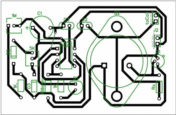
PCB Layout
Comments
do you have any soft file for the PCB layout?
Sorry, soft file is not currently available. I would recommend not to go for a PCB, instead test the unit on a Veroboard PCB first and verify the results…
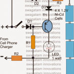
It is possible to use this charger to charge mobile phones with an induction charging system
And what is the data of the capacitors that are connected to the transmission coils and the receiver
Yes, that’s possible.
You can try the concept explained in the following article:
https://www.homemade-circuits.com/wireless-cellphone-charger-circuit/
to charge a phone how many turns for the coil
Hi,
do you have any idea about long distance wireless charging?
I need to charge a radiotransmitter on a car the car is in parking (no one on board).
Thanks
Hi,
Long distance wireless charging is not a feasible concept according to me.
How many turns of coil should I do ?
It will need to be experimented…
hello sir can does it support 24 v dc and if not what can we do so it will work thankyou
Hello student, you can use 24V, but the number of turns of the coil will also need to be increased appropriately…you will have to do it through some trial and error approach
is this circuit will work for 48v dc output ??
yes, but the IC 555 section must be supplied with a 12V.
Do you sell kits to build the generator?
No!
Hi, I’m Talha, living in Turkey.
I need to help for wiriless charging. I builded a charging system but it’s not working.
If you read this mail, basicly;
I want to make a table with invisible charging system. I have a work table and i cant ream to table for pick to my qi wiriless charging system beacuse my mom dont permission ream table. So that i search how i do it. Finally i decide to using lc tank coil up to the table and paste to qi wiriless charger under table. But my phone dont get charging.
I use flat coil has 12 cm radius with connected 5 units 0.1 uf non polar capacitor. I do only check lamp.
Please send me remail.
Thank you for reading.
Hi, you can try the concept presented in the following article, which is a self oscillating type configuration. However you will have to optimize the supply voltage, number of turns and current.
https://www.homemade-circuits.com/wireless-cellphone-charger-circuit/
Thank you for reaply Matrix.
Firstly i tried your link circuit and i have big problems. For example if i use 2 core wire and tip35 transistor, tip35 it gets very hot. How can fix tip35 hotting?
Hi Talha, the transistor will get hotter if it gets saturated due to over voltage or over current. Therefore try reducing the voltage until the output is optimized correctly, and until the transistor does not heat up too much. However, the transistor will need a heatsink to work correctly.
Dear Swagatam Sir,
I have a situation where i need to power a timer 555 without wires i can certainly see the above circuit will do the job (great innovation). However, i have about 10, 555 timers that need to be powered wireless-ly. In that case the LC of all the 10 will fall in parallel, will that work? I can see a power transistor like 2N3055 may take the load, but how do i match the LC’s. what will be the receiver side LC? Thank you in anticipation.
Thank you Shirish, for powering 10 circuits, 10 separate LC units may not be required. You can use a single LC network, and power all the 10 circuits from the single LC unit. Just make sure the LC network of the Tx and RX are adequately rated to handle the current consumption of the 10 circuits
Dear Sir
It is appreciable work done by you i really like your design and calculations.
i am not professional in electronics and i wish to make this,
i just have little small query about this project,
you used some coils as transmitter coil and receiver coil but i can’t find the coil making details or any size or any datasheet i mean how can i make those coil by my self.
also i want to know that how many voltage and amps we can get from this when we give input 11.1vdc 2.6a supply
Hi Ashish, the coil, capacitor and frequency values are interrelated, so they will need to be adjusted with trial and error for peak resonance. Or if you know the frequency and the capacitor values, then you can calculate the corresponding resonance frequency with the help of the following formula
f = 1 / 2π x √LC
where L is the inductance in Henrys, and C is the capacitance in farads, frequency in Hertz
The coil can be as given in the following image:
https://www.homemade-circuits.com/wp-content/uploads/2015/09/wireless-battery-768×415.jpg
the output V x I will almost equal to the input V x I
Hi Sir, can it be possible to create a circuit that can transmit a distance of 5meters to the reviewer?
Hi Majaha, as the distance is increased the efficiency will get affected drastically, so it may not be possible. And 5 meters is very high, no chance even with the most advanced technology
Hi swagtam, can it be upgraded to a push pull topology using NPN & PNP Transistors?
It can be done, you will need a dual supply in that case
Diode at 1K resistor end (to ground) is it 1N4148 or another ? Please answer..!
That’s an LED (optional)
Good day sir.
Well I have built the circuit (for simulation) but I’m getting a very low AC voltage at the output (thats at coil, inductor). I’m getting mV (around 7mV to be more specific), I would like to get at least 10V. But now I dont know how to get it, I would appreciate your help sir.
Thank you for the great circuit.
Hope to hear from you soon…
Hi Garp, I never use simulators so I do not know much about them. Is your simulator showing amplitude variations in response to frequency adjustments? Make sure the optimization produces maximum amplitude aross the transmitter tank LC network…and if the receiver LC tank circuit is also optimized with the same LC values then it will also resonate.
Dear
I would like to mount this PCB Layout for testing on a wireless smartphone charger!
Could you please give me the list of components for this?
Thank you very much
For smartphone, the PCB will need to be very compact, thin and correctly calculated. If possible I may update it some time in near future.
By saiying “Rx = 0.6/Max current Limit of the transistor (or the wireless power transfer)” do you mean that if I need to transmit 5A over the coils, Rx = 0.6/5 = 0.12?
What unit would 0.12 be? Ω or kΩ?
P.S. : I need to wirelessly charge a 5A 22.2V LiPo battery, do you think this circuit can handle it?
Thanks
Yes that’ right, it will be 0.12, in OHMs. The formula is the basic Ohm’s law so the output will be always in Ohms, provided the current is taken in Amps and voltage in volts.
5A 22V wireless charging is certainly possible, but for this the input current will need to be above 5 amps, may be 7 amps, and the coil wires will need to be upgraded accordingly
There are a few more things i’m not sure about :
– Calculating the IC555 frequency with 5k & 1M pot gives me a 1Hz to 300Hz frequency range. Isn’t that too low? Most QI charger on the market are in the KHz – MHz range…
– What’s the connection between the IC555 frequency and the LC frequency? Do they need to be identical?
– You say the PWM pot (5k pot) can adjust the current, isn’t the current decided by the load (receiver?)
Thanks for your help
You are right, please reduce the capacitor value to 1 nF.
The 555 frequency must be adjusted to the LC resonance frequency for optimal performance.
The PWM restricts the output current regardless of how much the load tries to consume, so it’s like putting a cap on the current consumption so that the load is unable to go beyond a certain limit.
The 2N2222 additionally does the same.
how to select transmitter coil and receiver coil for wire less charger for 3.3 v to 12 v dc battery with auto charger ?
The procedures and calculations are given in the article, you can easily work it out according to your requirement.
Good Morning Sir,
I want to attempt this project so, I would like to know this project is hardware implemented or not?
Hi Bangaru, the concept has been tested using a different oscillator but not yet tested using IC 555
Dear Boss,
please support with Value of capacitor and resistance
also i need to make circuit for wireless battery 3Vdc charger.
mention circuit in this page can be implement the required ( wireless battery 3Vdc charger.)
thanks for kindly support
Ahmad, the frequency and the tank capacitor will need to be found out by practical experimentation, and this will depend on the selected coil turns and inductance value. These can be tweaked and finalized only by piratical tests.
what are the practical tests?
also how to measure the inductance value of the coil
Inductance can be calculated using the following formula
L = (0.2 x d2x N2) / (3d + 9l =10b)
L = Inductance (in μH)
d = Diameter of the inductor coil (Inches)
l = Length of the indutor coil (inches)
b = Diameter of the coil winding wire (inches)
N = Total turns of wire
SORRY, this is for a normal coil not for bifilar coil…I’ll let you know soon
Did you manage to find the formula for the bifilar coil?
No I couldn’t find it, however it seems a bifilar coil is not required for the above circuit. A normal single core wire tightly wound is enough
Hello Meera, the distance should be within an inch, beyond this the power transfer will keep decreasing proportionately
Sir can you tell me the limit of distance between the transmitter & receiver for effective power transfer?
you will have to calculate them with respect to the frequency….the software link for calculating is provided in the article. The frequency is created by the IC 555 circuit and adjusted by the accompanied pot.